


|
|
LED 5mm Red |
x 14 | |
|
|
resistor 220 ohmstriark
|
x 8 | |
|
|
resistor 10k ohmstriark
|
x 3 | |
|
|
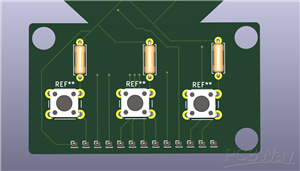
tactile push button 6mmaliexpress
|
x 1 |
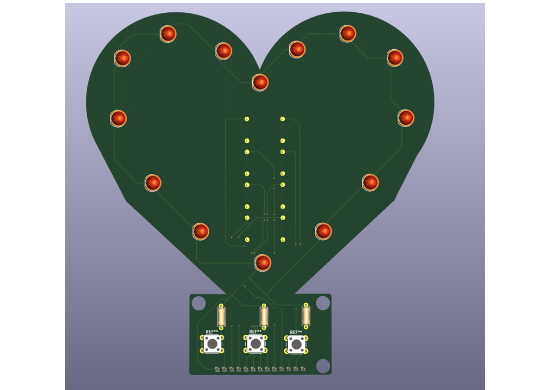
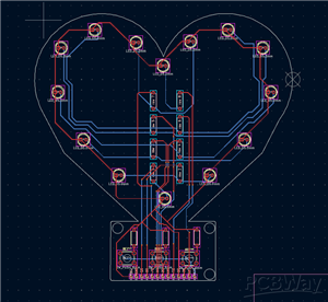
a heart led board
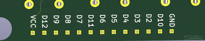
so this PCB does not come with a place for it but you will need a microcontroller and at the bottom each one of the holes have a diameter of 5mm in case you need a place to crew a box with a microcontroller and/or a battery. so basically each led is connected in rows to one of the digital pins labelled and they are all connected at the pin headers at the bottom. the code is posted on here too so this code makes it so the button on D10 constantly keeps the LED's on without a pattern, the middle button (D11) is a pattern where the LED's chase each other to the top, and finally the 3rd button is a heartbeat. this is optional however and you can create your own code but just in case I posted it too. This can be used as a night light or just a present to give to someone its really up to you.
const int ledPins[] = {2, 3, 4, 5, 6, 7, 8, 9};
const int btnPins[] = {10, 11, 12};
int mode = 1;

// Memory for button states
bool lastBtnState[] = {HIGH, HIGH, HIGH};

unsigned long lastTime = 0;
int step = 0;

void setup() {
  for (int i = 0; i < 8; i++) pinMode(ledPins[i], OUTPUT);
  for (int i = 0; i < 3; i++) pinMode(btnPins[i], INPUT_PULLUP);
}

void loop() {

  for (int i = 0; i < 3; i++) {
    bool currentState = digitalRead(btnPins[i]);


    if (currentState == LOW && lastBtnState[i] == HIGH) {
      mode = i + 1;
      step = 0;
      clearAll();
      delay(50);
    }
    lastBtnState[i] = currentState; // Remember for next time
  }


  unsigned long now = millis();
  if (mode == 1) {
    for (int i = 0; i < 8; i++) digitalWrite(ledPins[i], HIGH);
  }
  else if (mode == 2) {
    if (now - lastTime >= 100) {
      lastTime = now;
      clearAll();
      digitalWrite(ledPins[step % 8], HIGH);
      step++;
    }
  }
  else if (mode == 3) {
    if (now - lastTime >= 200) {
      lastTime = now;
      step = !step;
      for (int i = 0; i < 8; i++) digitalWrite(ledPins[i], step);
    }
  }
}

void clearAll() {
  for (int i = 0; i < 8; i++) digitalWrite(ledPins[i], LOW);
}
a heart led board
*PCBWay community is a sharing platform. We are not responsible for any design issues and parameter issues (board thickness, surface finish, etc.) you choose.


Raspberry Pi 5 7 Inch Touch Screen IPS 1024x600 HD LCD HDMI-compatible Display for RPI 4B 3B+ OPI 5 AIDA64 PC Secondary Screen(Without Speaker)
BUY NOW


- Comments(0)
- Likes(2)
 More by Engineer
-
Programmable Mist Maker - XIAO / QT PY Extension
867 1 0 -
RadioHAT - Raspberry Pi radio development platform
694 0 2 -
-
-
-
-
ARPS-2 – Arduino-Compatible Robot Project Shield for Arduino UNO
3166 0 6 -
A Compact Charging Breakout Board For Waveshare ESP32-C3
3782 3 8 -
AI-driven LoRa & LLM-enabled Kiosk & Food Delivery System
4122 2 2


