


"WHAMMY" Pass DIY headphone amp
https://www.diyaudio.com/forums/pass-labs/317803-whammy-pass-diy-headphone-amp-guide.html
PSU
Transformer 15VA or 25VA 15+15 to 22+22
25VA 22V+22V is best and used in this guide.
Currently the transformers that fit the board are available at Digikey
Amgis 6663, 6664 / Amveco 70053
Here's a link to a factory surplus transformer that fit the PCB will work beautifully - You will want to make R16, R22, R29, R32 15ohm if using this transformer.
70054K PC Mount Transformer 110/230V-18/36V 110V-36V 110V-18V 230V-18V 230V-36V
There are pads on the PCB for a non-PC mount transformer if you have room in your chassis. Something like an Antek AN-0220 or AN-0222 would work well. AN-0220 - 25VA 20V Transformer - AnTek Products Corp
If you use smaller transformer you may need to adjust the bias down a bit. It will still be pure class-A for 99.999999999% of all headphone listening.
The bridge is made from 1N4004 or use high speed diode if you like. Snubber capacitor C20 0.22uF 250v X-rated.
AC filtering is done in a big and effective way, utilizing a CRCRC filter with 3300uF capacitors and 5.1ohm resistors. You can use smaller resistors and caps if you like, it's a very effective filter and will work well with even 1/2 the values.
The regulators using 7815/7915 can be elevated a bit, using a red or green LED as the reference if you wish. Don’t use blue, they are noisy and they will set the regulators to too high of a voltage.
Circuit
On the input there is a dual opamp used for voltage gain. We’ve tried these with great success LM833, Muses 8820, RC4580, OPA2604, AD823, TL072.
If you want to try a different opamp, try something made for audio. Feel free to try some surface-mount opamps in a DIP adaptor if you like, there are lots of neat opamps to try.
Gain is set by R8/R12. Lower gain, make R12 bigger, unity gain, R12=10K
Potentiometer - Alps RK27 fits the PCB, feel free to use what you like. If you have room in your chassis, this is a fine place for a stepped attenuator.
After the opamp there is a Mosfet source follower for current capibility, and the feedback loop includeds the opamp. This keeps the DC offset stable as well as lowers the output impedance to a very low level, less than 1/10 of an ohm.
Output stage
The output stage is a Mosfet NP pair in source-follower configuration. Being a follower it can add no voltage to the signal but can contribute lots of current. Since the opamp os being used for gain this is not problem. It also has the advantage of adding very little sonic flavor to the signal, it's esentally transparent. The output stage is simple, powerful, will drive anything, and is self adjusting due to optocoupler and the opamp controls DC offset because the output stage is in the feedback loop. No potentiometers to adjust or voltages to read when biasing.
Output impedance is less than 1/10 ohm
The following Mosfets work well in the circuit.
Toshiba Mosfet 2SK2013 / 2SJ313
Fairchild Mosfet On Semiconductor Fairchild FQP3N30 / FQP3P20
IRF Mosfet Vishay IRF610PBF / IRF9610PBF
No matching is required.
Bias arrangement (low offset due to opamp precision)
(4) 10K resistors make a voltage divider to give lots of bias voltage to the gates; this bias will be 1/2 the rail voltage. Assuming a standard build with 17v rails this will give the Mosfets a maximum of 8.5v of bias. With no other controls his would make the output devices conduct like there’s no tomorrow, and probably let the smoke out, but the 4N35 optocoupler helps control and set the necessary bias voltage. With this it happily operates in Class-A all the time.
The 4N35 optocoupler does a few things -
The optocoupler has two sides when looking at the schematic, the diode and the transistor. They are linked optically, not electrically, so the two sides of the optocoupler can share different voltages that don't effect the other side. as the current change in the LED side of the opto it will glow brighter or dimmer, which controls how much the transistor side conducts - in this circuit the current through the LED is directly equal to the mosfet current, and as it gets brighter it controls the BJT, whereby the BJT "burns up" the excess dc bias voltage.
The optocoupler appears to be a variable resistor in parallel with the inside 10k resistors - it changes the gate bias with the collector-emitter junction as the opto coupler looks at the current through the mosfet sources. The LED part of the opto has a 1.2v constant drop, this is used in conjunction with R18 to set bias current across the source resistors. If the current is too high it will make the LED brighter, that modulates the base of the transistor, and the collector-emitter junction will decrease its apparent resistance in parallel with the inside 10k resistors, changing the ratio of rail voltage to ground, decreasing the amount of voltage on the gates, and keeping the bias stable as the load swings.
Is a simple solution - its a single part and it automatically adjusts. If there is any drift the optocoupler will compensate immediately No resistors to measure across and potentiometers to adjust
Output bias
The diode in the 4N35 gives voltage across source resistors to set current, a 1.2V reference.
Total source R is added, so 10R resistors is 1.2V/20R=60mA
Want more bias? make the resistors smaller. 4.7R = 120mA
"WHAMMY" Pass DIY headphone amp
*PCBWay community is a sharing platform. We are not responsible for any design issues and parameter issues (board thickness, surface finish, etc.) you choose.


Raspberry Pi 5 7 Inch Touch Screen IPS 1024x600 HD LCD HDMI-compatible Display for RPI 4B 3B+ OPI 5 AIDA64 PC Secondary Screen(Without Speaker)
BUY NOW


- Comments(0)
- Likes(4)
More by John Sparrow
-
 Nixie bargraph thermometer with Arduino
Besides the well known numerical nixie tubes, other types of neon filled tubes were also used in the...
Nixie bargraph thermometer with Arduino
Besides the well known numerical nixie tubes, other types of neon filled tubes were also used in the...
-
 Сirklotron with germanium transistors Darlington output.
Forum:https://www.diyaudio.com/forums/solid-...
Сirklotron with germanium transistors Darlington output.
Сirklotron with germanium transistors Darlington output.Forum:https://www.diyaudio.com/forums/solid-...
-
 Speaker Turn-On Delay and DC Protector
Speaker protection with galvanic isolation from the amplifier.
Speaker Turn-On Delay and DC Protector
Speaker protection with galvanic isolation from the amplifier.
-
 YES-4M-SAB amplifier
Forum thread:https://forum.vegalab.ru/showthread.php?t=81794
YES-4M-SAB amplifier
Forum thread:https://forum.vegalab.ru/showthread.php?t=81794
-
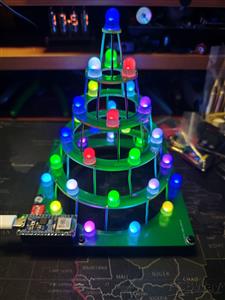 Christmas tree
Circular Christmas tree 2023(C) Elektor
Christmas tree
Circular Christmas tree 2023(C) Elektor
-
 Delay Power On
Device for delaying the supply of anode voltage in tube power amplifiers. The delay time is adjustab...
Delay Power On
Device for delaying the supply of anode voltage in tube power amplifiers. The delay time is adjustab...
-
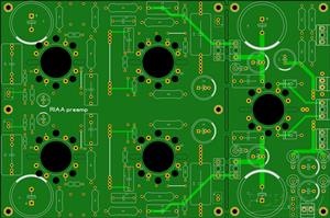 MM RIAA preamp 6Ж38П - 6Н6П
RIAA preamp 6Ж38П - 6Н6ПAlmost universal printed circuit board on which you can collect RIAA preamp.
MM RIAA preamp 6Ж38П - 6Н6П
RIAA preamp 6Ж38П - 6Н6ПAlmost universal printed circuit board on which you can collect RIAA preamp.
-
 MM RIAA preamp EF86 - ECC88
RIAA preamp EF86 - ECC88Almost universal printed circuit board on which you can collect RIAA preamp.
MM RIAA preamp EF86 - ECC88
RIAA preamp EF86 - ECC88Almost universal printed circuit board on which you can collect RIAA preamp.
-
 "The End Millennium" clone amplifier
Amplifier Millennium v4
"The End Millennium" clone amplifier
Amplifier Millennium v4
-
 JFET Circlotrons without NFB KP-3
Power supply: https://www.pcbway.com/project/shareproject/Power_sup...
JFET Circlotrons without NFB KP-3
JFET Circlotrons without NFB KP-3Power supply: https://www.pcbway.com/project/shareproject/Power_sup...
-
 Power supply for JFET Circlotrons without NFB KP-3
Stabelized power supply for JFET Circlotrons without NFB KP-3
Power supply for JFET Circlotrons without NFB KP-3
Stabelized power supply for JFET Circlotrons without NFB KP-3
-
 Amplifier "Yes-6"
Audio amplifier "Yes-6".https://forum.vegalab.ru/showthread.php?t=90816
Amplifier "Yes-6"
Audio amplifier "Yes-6".https://forum.vegalab.ru/showthread.php?t=90816
-
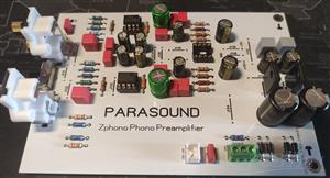 RIAA MM/MC preamplifier Parasound Zphono
RIAA preamplifier Parasound Zphono
RIAA MM/MC preamplifier Parasound Zphono
RIAA preamplifier Parasound Zphono
-
 Loudspeaker Testing Jiq
Features and Specifications- Measures loudspeaker driver frequency and phase responses- Measures lou...
Loudspeaker Testing Jiq
Features and Specifications- Measures loudspeaker driver frequency and phase responses- Measures lou...
-
 Salas folded simplistic phono
https://www.diyaudio.com/community/threads/simplistic-njfet-riaa.129126...
Salas folded simplistic phono
Salas folded simplistic phonohttps://www.diyaudio.com/community/threads/simplistic-njfet-riaa.129126...
-
 Amplifier "Yes-7"
Audio amplifier "Yes-7".Published with the permission of the author.Link to the for...
Amplifier "Yes-7"
Amplifier "Yes-7"Audio amplifier "Yes-7".Published with the permission of the author.Link to the for...
-
 Amplifier "Yes-7"
Audio amplifier "Yes-7".Published with the permission of the author.Link to the forum (russian) with...
Amplifier "Yes-7"
Audio amplifier "Yes-7".Published with the permission of the author.Link to the forum (russian) with...
-
 Salas UltraBiB shunt regulator with LT4320 diode bridge
My version of tracing printed circuit boards Salas UltraBiB shunt regulator.PCB are not for commerci...
Salas UltraBiB shunt regulator with LT4320 diode bridge
My version of tracing printed circuit boards Salas UltraBiB shunt regulator.PCB are not for commerci...
-
Programmable Mist Maker - XIAO / QT PY Extension
222 0 0 -
RadioHAT - Raspberry Pi radio development platform
250 0 1 -
-
-
-
-
ARPS-2 – Arduino-Compatible Robot Project Shield for Arduino UNO
2801 0 5 -
A Compact Charging Breakout Board For Waveshare ESP32-C3
3307 3 8 -
AI-driven LoRa & LLM-enabled Kiosk & Food Delivery System
3587 2 2


