


|
|
SSD1306 I2CDispaly Module
|
x 1 | |
|
|
Seeed Studio XIAO ESP32 S3 |
x 1 | |
|
|
ALS31313KLEATR-JOYAllegro MicroSystems
|
x 1 | |
|
|
MAX30102EFD+TMaxim
|
x 1 | |
|
RC0201JR-13100KLYAGEO
|
x 2 | |
|
|
ButtonC&K
|
x 3 | |
|
|
LiPo Battery |
x 1 |

|
arduino IDEArduino
|
|
|
|
Easy Eda |
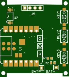
Gerber_myWatch1_PCB_myWatch1_2026-05-07
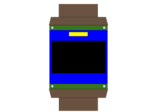
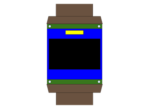
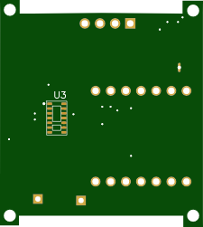
This project is very important to me because it represents the culmination of multiple weeks of designing and redesigning to make my first custom PCB. It uses a SEEED ESP s3 to run the watch. This is responsible for syncing with chosen wifi network, and it also has bluetooth connectivity. There are nearly endless implications to this, like time syncing and fetching the weather, reading messages from your phone, and controlling other home devices from your watch. Additionally, this microcontroller handles recharging, and I just attached the pads to two pots at the bottom of the pcb design, you may have to change around the schematic if you cannot solder on the battery yourself after production.
The other features include a 3d linear Hall effect sensor, which I primarily intend to use asa compass but it likely clnhvae other uses as well, up to you! The most practical sensor in this smartwatch is the max30102, which measures your heart rate, this sensor is assembled facing the other side of the board sort is touching your skin.
Finally, there are three buttons, ideally two for scrolling and one for selecting options on a menu, but again this is up to you since the software is open source so you make your own OS. If you are not into coding, I have also found that language models like Claude or ChatGPT are very good at coding theses things with an accurate pinout description and a little guidance.(I will attach pinout at end of writing)
|Button |XIAO Pin|GPIO |Other leg|
|--------|--------|------|---------|
|BTN_UP |D0 |GPIO2 |GND |
|BTN_SEL |D1 |GPIO3 |GND |
|BTN_DOWN|D9 |GPIO20|GND |
I2C Bus (all shared)
|Component|Pin|XIAO Pin|GPIO |
|---------|---|--------|-----|
|SSD1306 |SDA|D4 |GPIO6|
|SSD1306 |SCL|D5 |GPIO7|
|ALS31313 |SDA|D4 |GPIO6|
|ALS31313 |SCL|D5 |GPIO7|
|MAX30102 |SDA|D4 |GPIO6|
|MAX30102 |SCL|D5 |GPIO7|
ALS31313 extras
|Pin |Connects To|
|----|-----------|
|VCC |3.3V |
|GND |GND |
|ADR0|GND |
|ADR1|GND |
|INT#|Leave NC |
|NC |Leave NC |
MAX30102 extras
|Pin |Connects To|
|------------|-----------|
|VDD |3.3V |
|VLED+ (both)|3.3V |
|GND |GND |
|PGND |GND |
|INT# |Leave NC |
|N.C. pins |Leave NC |
Power & Battery
|Connection |XIAO |
|------------------|---------------|
|LiPo + |BAT+ pad (back)|
|LiPo - |BAT- pad (back)|
|Battery ADC middle|D10 (GPIO21) |
Battery voltage divider
LiPo + ── 100kΩ ── D10 ── 100kΩ ── GND
Gerber_myWatch1_PCB_myWatch1_2026-05-07
*PCBWay community is a sharing platform. We are not responsible for any design issues and parameter issues (board thickness, surface finish, etc.) you choose.


Raspberry Pi 5 7 Inch Touch Screen IPS 1024x600 HD LCD HDMI-compatible Display for RPI 4B 3B+ OPI 5 AIDA64 PC Secondary Screen(Without Speaker)
BUY NOW


- Comments(0)
- Likes(0)
 More by Engineer
-
Programmable Mist Maker - XIAO / QT PY Extension
835 1 0 -
RadioHAT - Raspberry Pi radio development platform
671 0 2 -
-
-
-
-
ARPS-2 – Arduino-Compatible Robot Project Shield for Arduino UNO
3131 0 6 -
A Compact Charging Breakout Board For Waveshare ESP32-C3
3761 3 8 -
AI-driven LoRa & LLM-enabled Kiosk & Food Delivery System
4088 2 2


