




|
Fusion 360Autodesk
|
Stationery Unit D2
Greetings everyone, and welcome back!
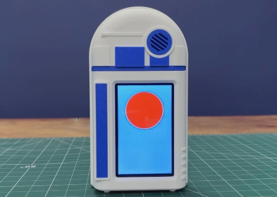
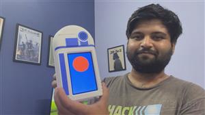
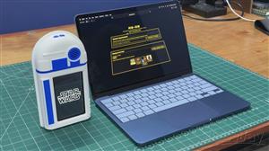
Here's something from beyond Stationery Unit D2, an R2-D2-inspired, interactive desk organizer and pen holder.
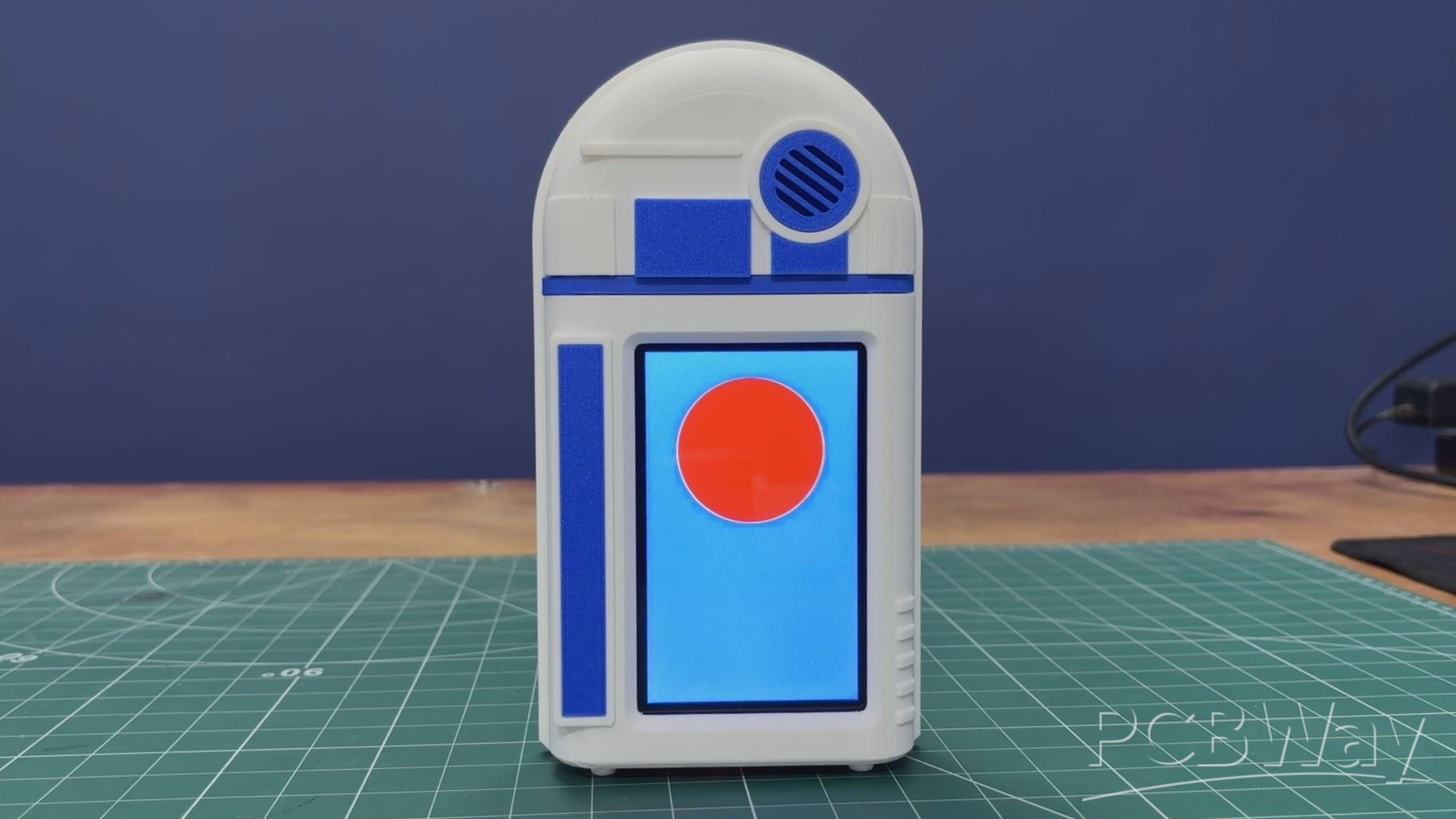
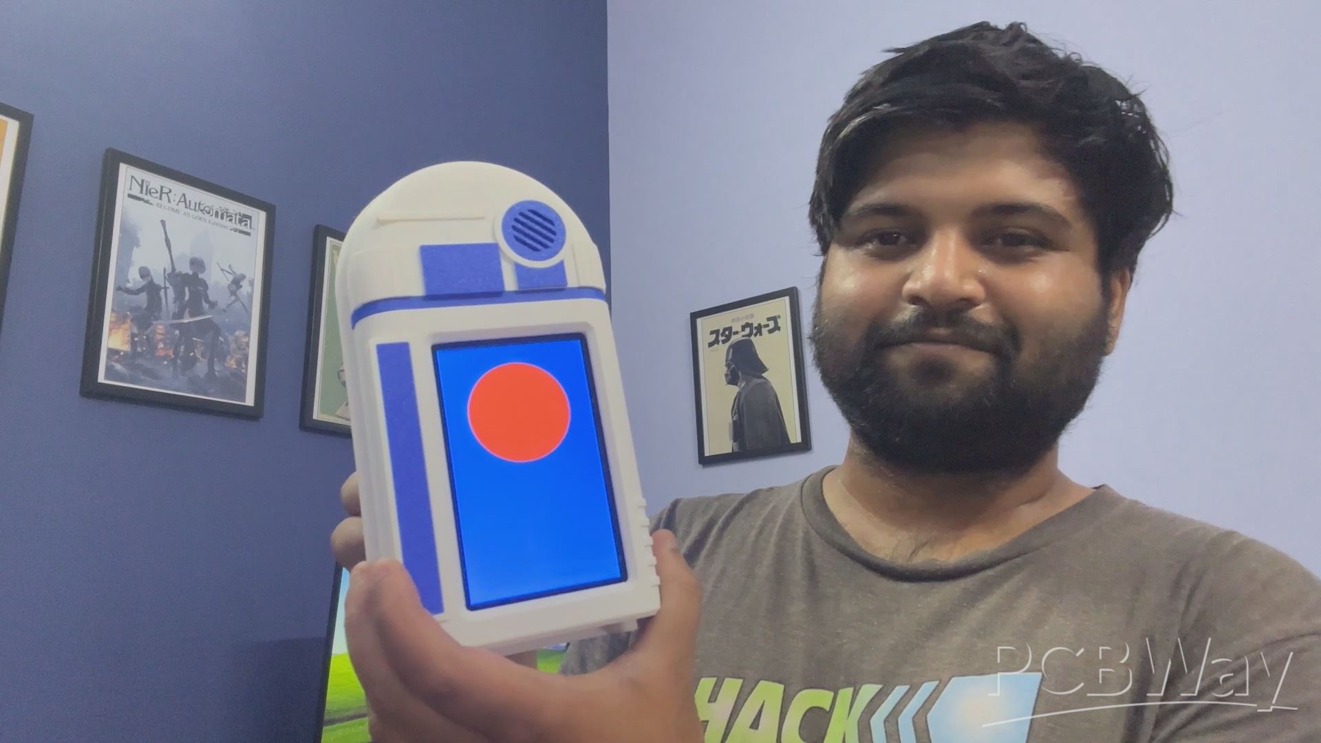
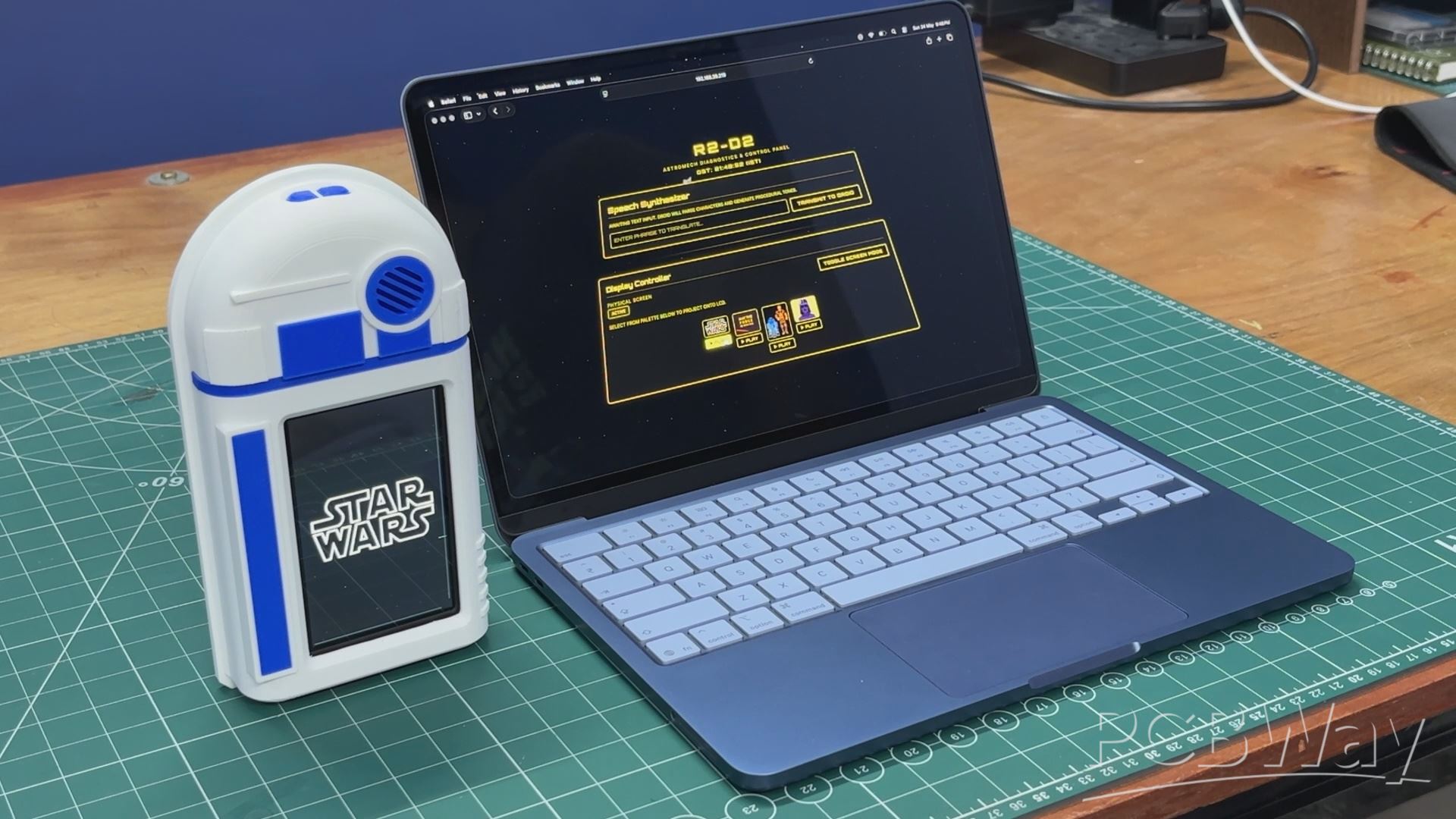
This isn't just a 3D-printed, R2-D2-looking pen holder; it’s an interactive, web-connected desk terminal powered by an ESP32-P4 dev board.
What really brings this droid to life is its behavior. I set up a background task in the code so the device generates life-like actions all on its own. Every 20 seconds, it plays a unique sequence of astromech beeps and chirps. It uses math to pick random frequencies, so it sounds like the droid is actually thinking or muttering to itself, making it feel truly alive.
I also wanted to make it easy to use, so I added two physical buttons on top. One button (GPIO 48) triggers fun "Easter Egg" songs I coded in, like the Star Wars theme and a few others, while the second button (GPIO 47) lets me instantly toggle the screen between a Radar UI and my favorite GIFs.
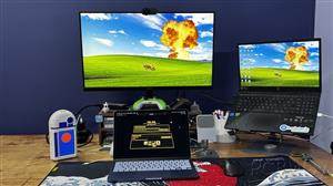
The web interface is where the real fun happens. Through the app, we can play GIFs on the ESP32-P4's display, trigger a cinematic Star Wars-style quote display, or even use the text-to-astromech converter to make the droid speak any message.
The design of this project was heavily inspired by R2-D2. Instead of creating a standard cylindrical R2-D2, I went with a flatter design that incorporates key visual elements from the original droid. The body was 3D-printed and then assembled.
This article covers the complete build process, from design and wiring to setting up the code and final assembly.
Let's get started.
MATERIALS REQUIRED
These were the materials used in this project-
- Custom PCBs (Provided by PCBWAY)
- Wavshare ESP32 P4 Dev Board with Touch Display
- Lithium Cell for Power source 3.7V 500mAh
- 3D Printed parts
- 4x4 Push Buttons
- Connecting Wires
- Speaker
- M2 screws
DESIGN
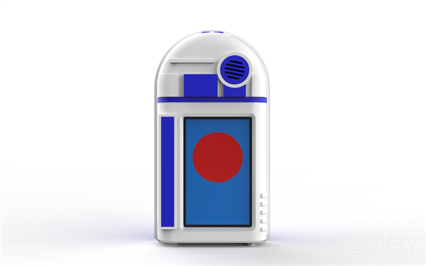
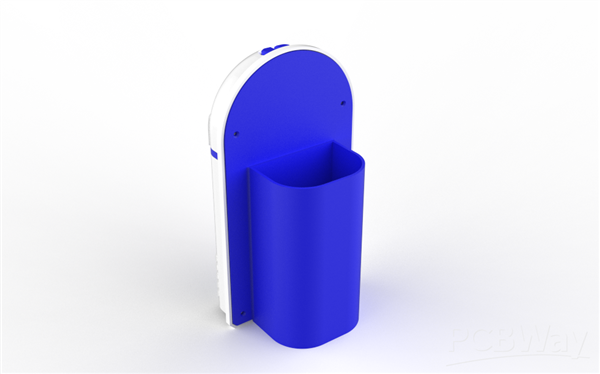
The entire model was designed in Fusion 360. While this project is heavily inspired by R2-D2, I didn't follow the original design entirely; I completely ditched the traditional cylindrical body in favor of a flat, modern aesthetic that still closely resembles the iconic droid.
For the internals, I incorporated a Waveshare ESP32-P4 development board, which features a 4.7-inch display positioned slightly off-center. My idea is to print a blue screen on the display with a red circle that resembles R2D2.
To capture that authentic droid aesthetic, I modeled greeble parts, which I’ll be printing in blue, and the body will be printed in white.
On the back, I added a custom lid section that functions as the pen holder, making sure the device stays practical while looking the part.
ENCLOSURE
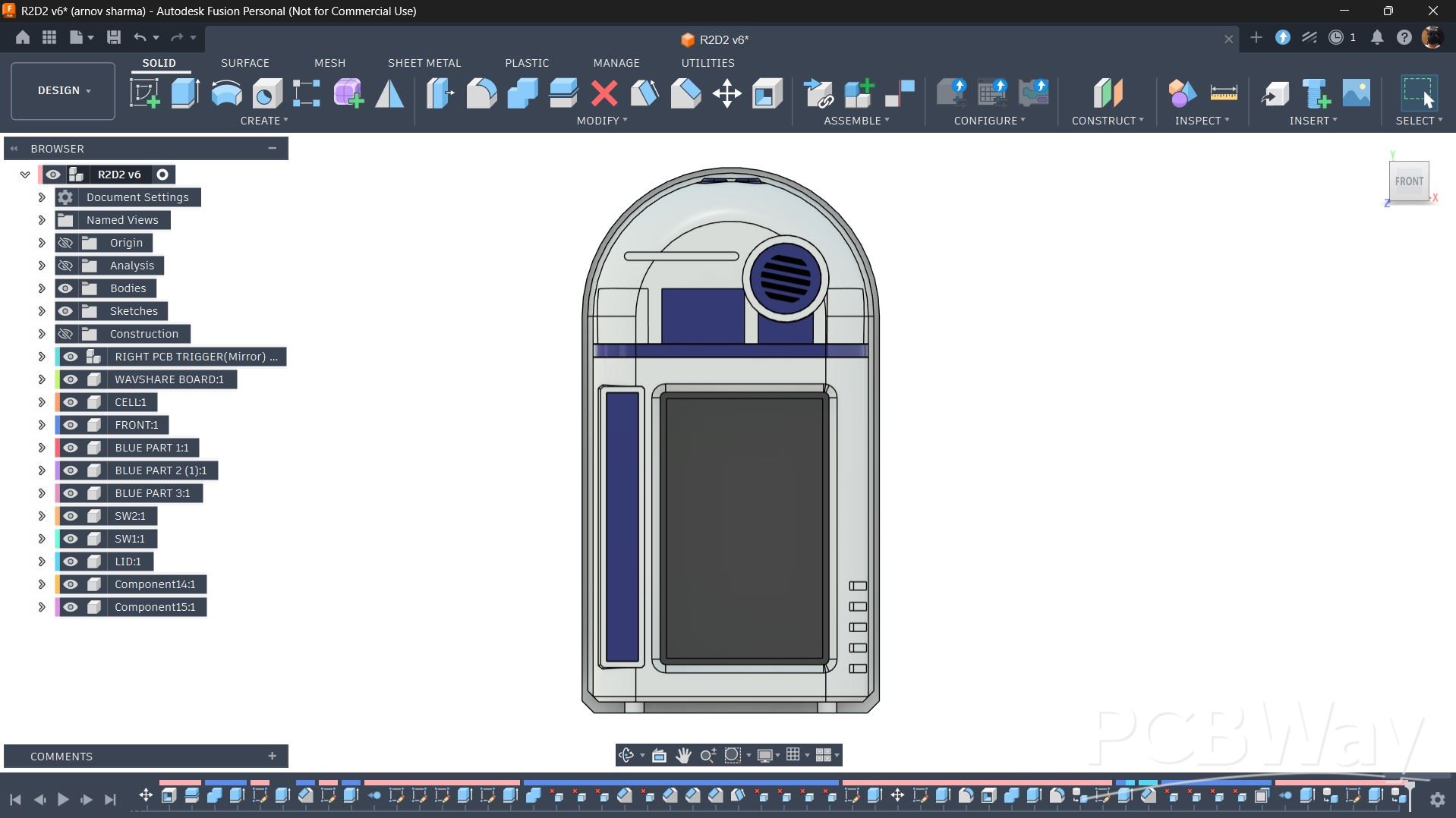
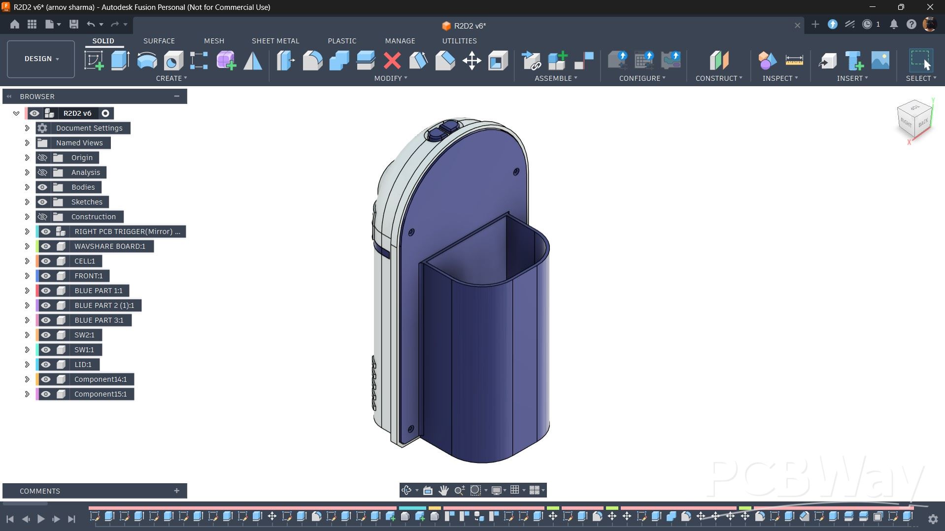
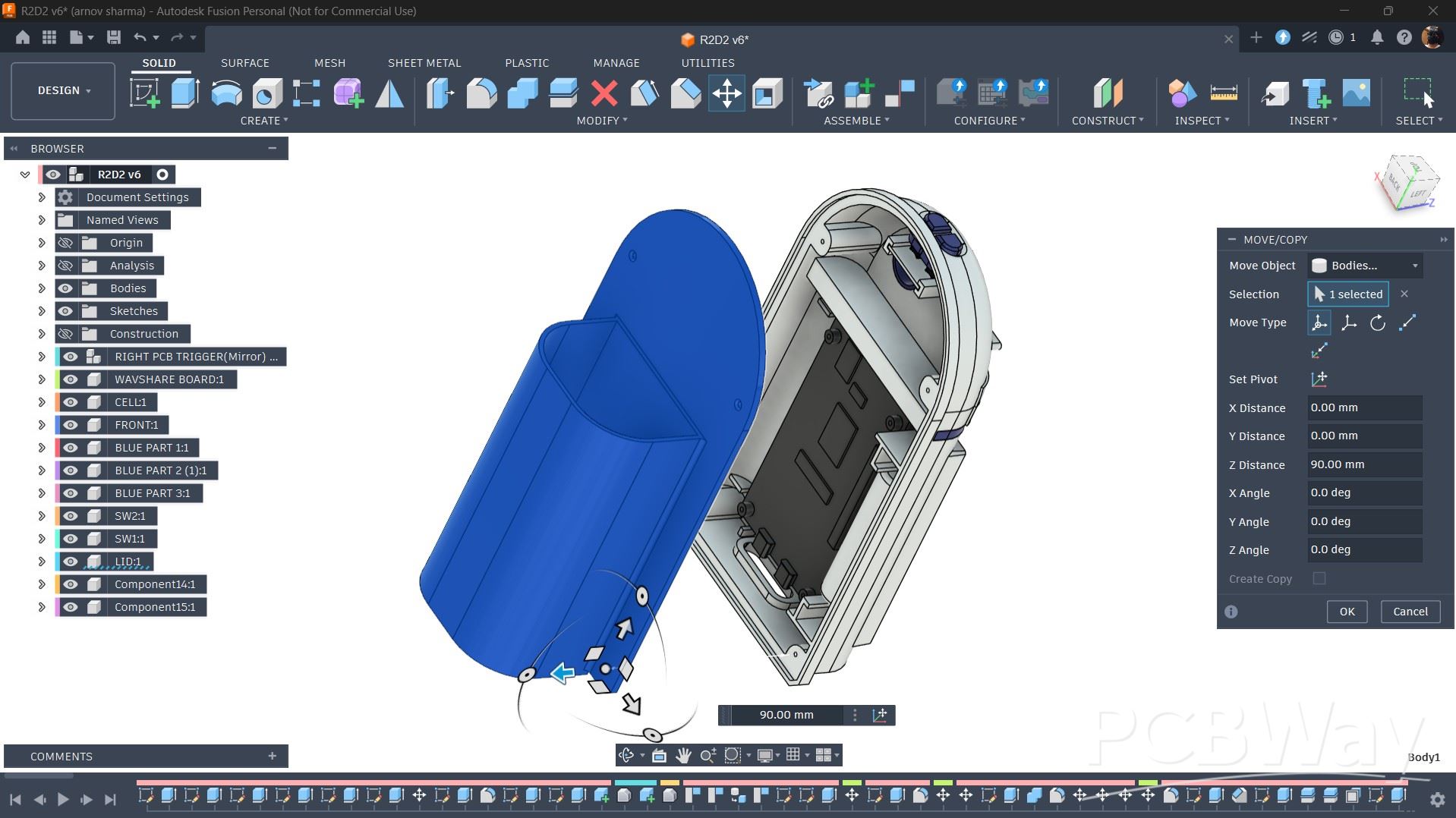
The enclosure of our design comprises two main parts: the front enclosure, which is designed to resemble R2-D2, and the back enclosure, which serves as a lid for the model while also incorporating the pen holder section.
Both the front and back enclosures are secured together using M2 screws.
SWITCH SECTION
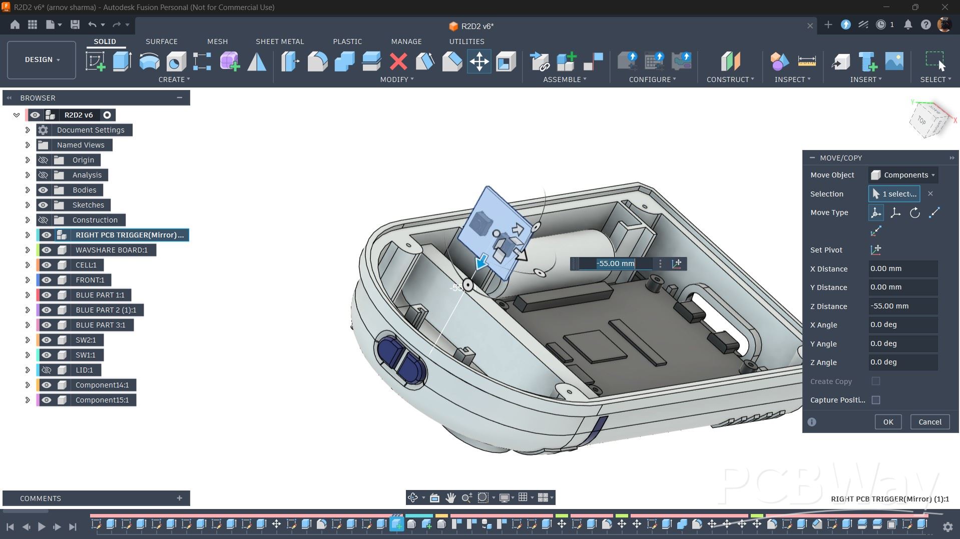
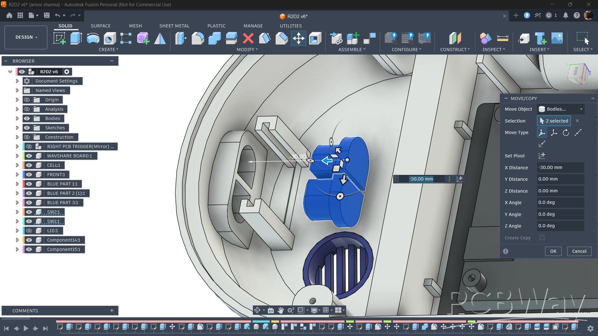
For adding controls, I incorporated two buttons into the design. The buttons are positioned on the top face of the model.
To mount them, I designed two retaining ribs that allow the switch PCB to slide into position securely. Before installing the switch PCB, two identical switch actuators are placed in their respective positions.
Once the switch PCB is inserted, the actuators are locked in place. Pressing these actuators activates the switches, registering the button press.
POWER SOURCE PLACEMENT
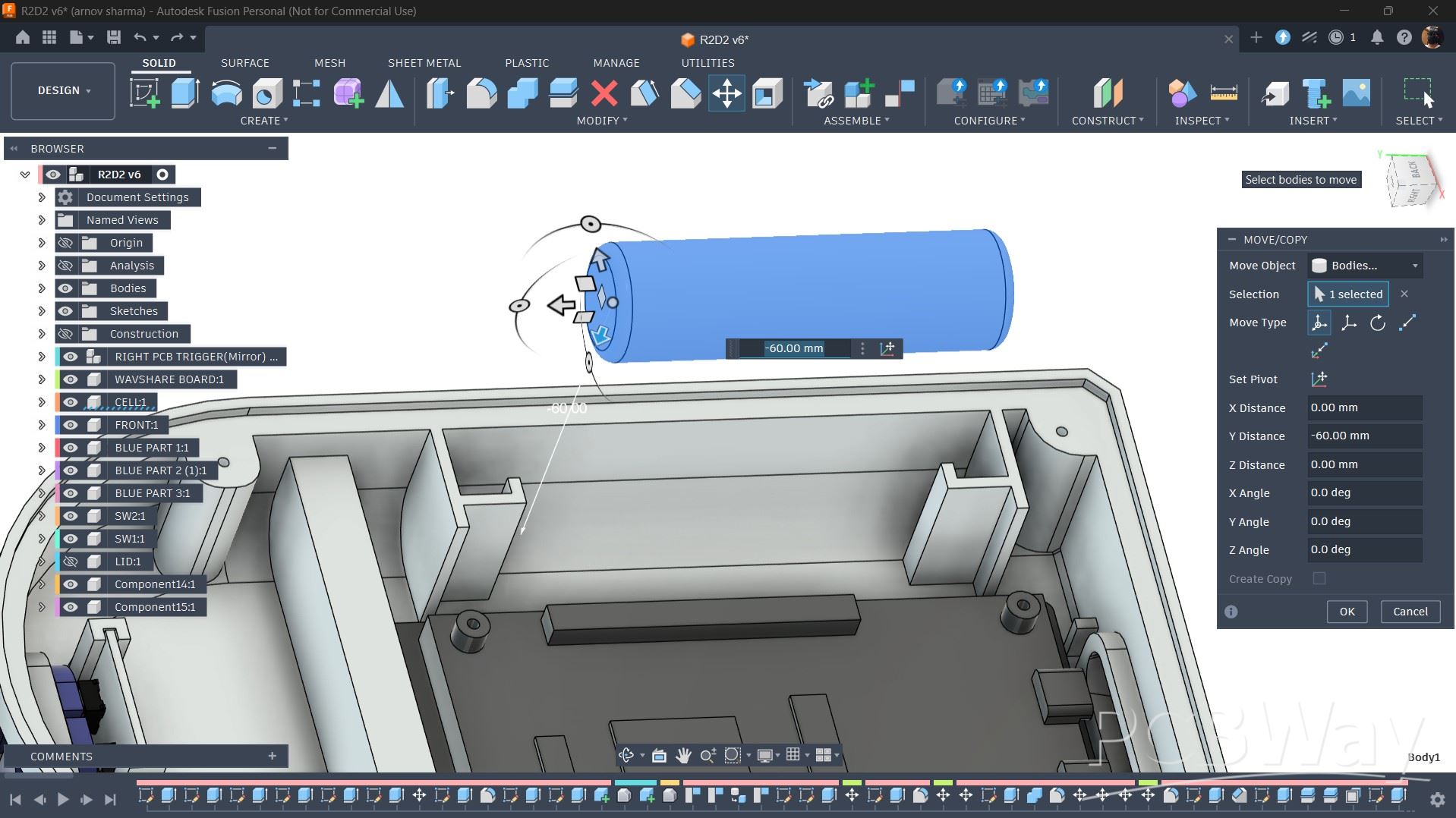
For the power source, I used a 3.7 V 500 mAh lithium-ion cell (size 14500), which is smaller than the more commonly used 18650 cell.
I positioned the battery on the opposite side of the display and added two ribs to keep it securely locked in place.
ESP32 P4 DISPLAY PLACEMENT
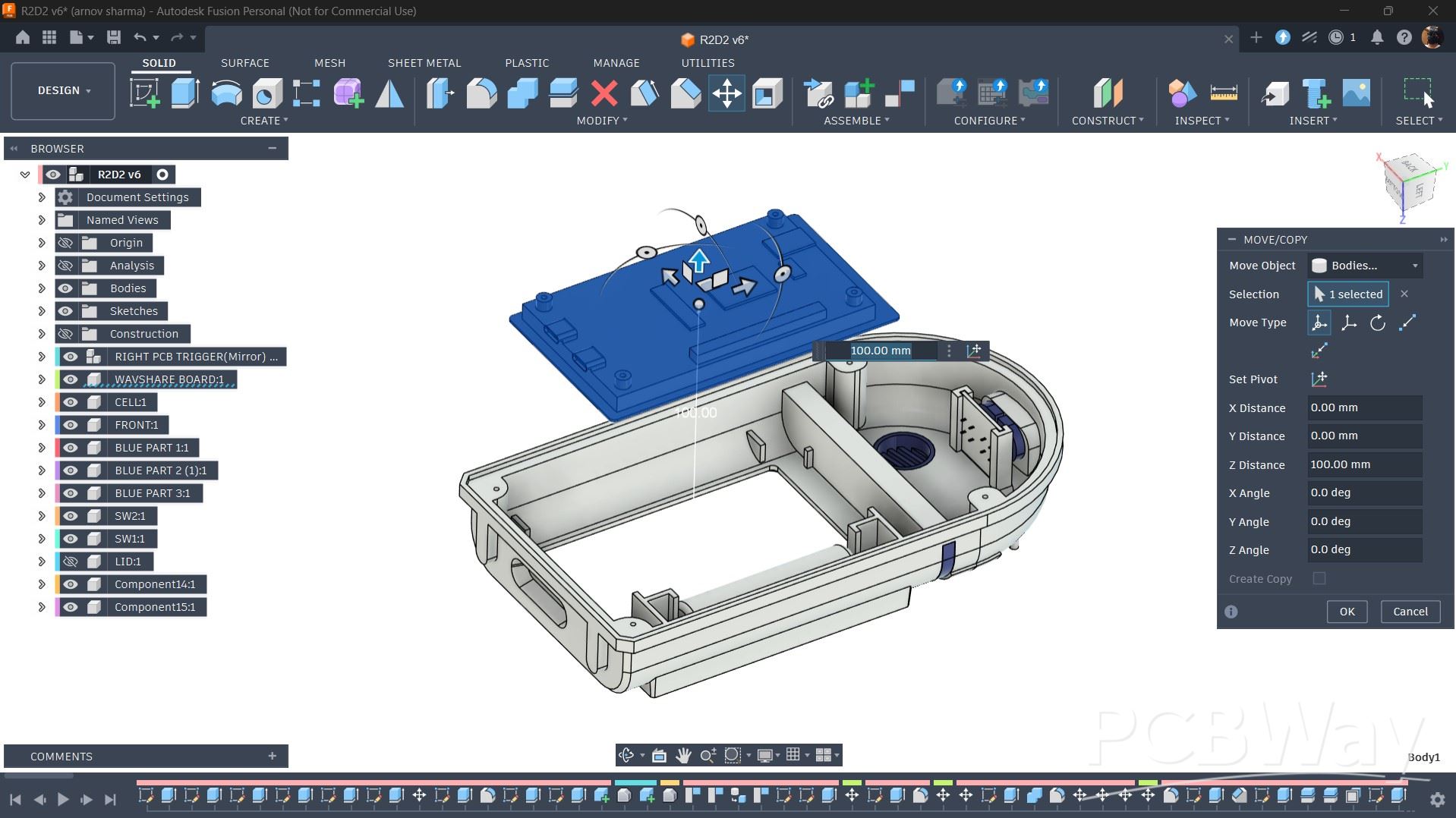
The ESP32-P4 Dev Board is placed slightly off-center. To keep it securely in position, I added several ribs that ensure the display does not move from its intended location.
GREEBLES PARTS
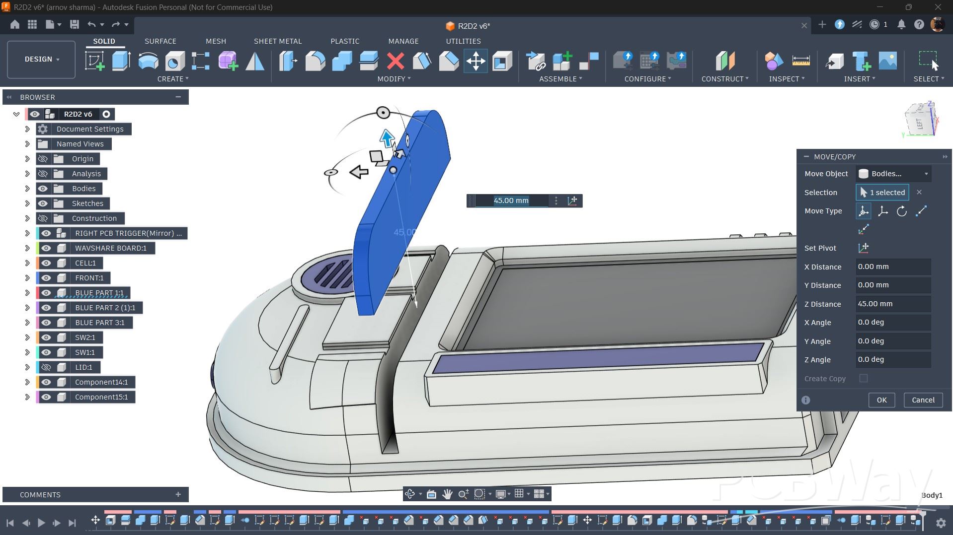
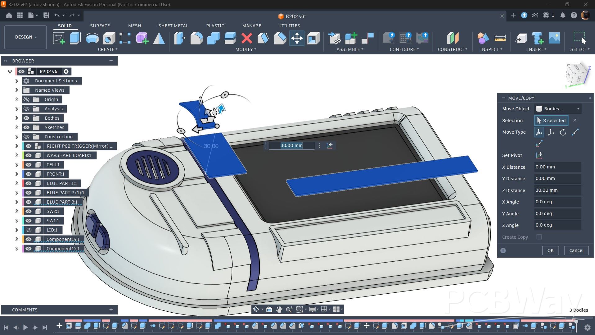
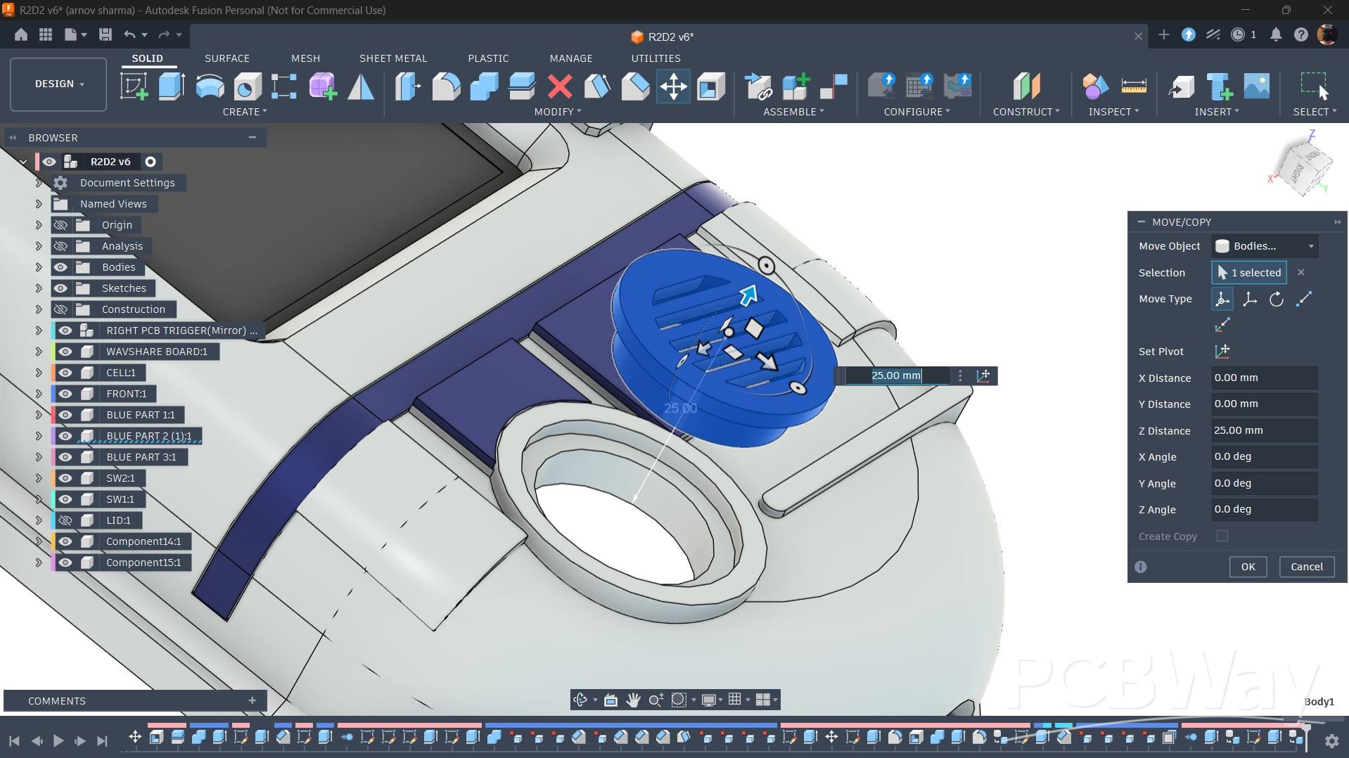
To make this device look and feel like a droid, I designed several greeble parts that would be printed in Blue PLA and then placed in position.
These include a part that sits between the screen and the head section, as well as a long part that sits next to the display.
Two additional parts are mounted on the top section slightly above the display, along with a circular grille part, all of which are printed in Blue PLA.
3D PRINTED PARTS
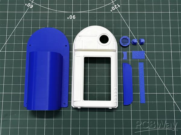
After finalizing the model, all parts were exported as mesh files and then 3D printed on my Anycubic Kobra S1 printer using two filament colors.
Blue Hyper PLA was used for the majority of the parts, including the back enclosure, greeble parts, and switch actuator.
White Hyper PLA was used for the front enclosure. All parts were printed with a 0.4 mm nozzle, 0.2 mm layer height, 25% infill, and no supports were required for the blue parts.
Only the front enclosure required supports, as it was printed upside down, so the inner parts of the model needed support.
PCB DESIGN
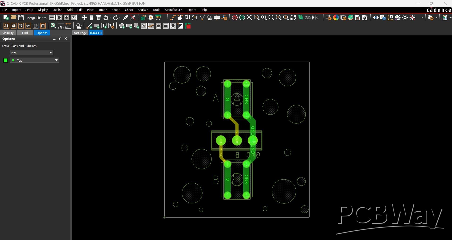
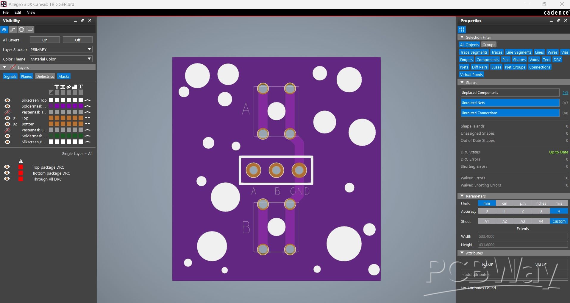
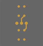
This is the Switch PCB we used in this project, and it's a simple one. Here, we have added two 4×4mm push buttons on a 20×20mm board. The placement of each button and the mounting holes are all positioned according to the 3D model.
A CON5 connector is also added. The first pin is connected to GND, and the remaining four terminals are connected to each button pin. Through this connector, we will later pair the UNIHIKER M10 with our button board.
BTW, we are reusing this PCB from a previous project, which you can check out from the link below.
https://www.hackster.io/Arnov_Sharma_makes/hitpad-6182e1
PCBWAY
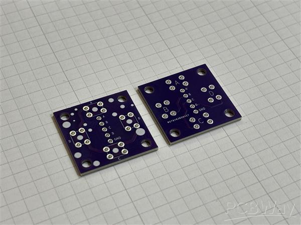
The Switchboard PCB was provided by PCBWay. I designed the PCB in my PCB design software and sent the Gerber files to PCBWay for fabrication. The PCBs arrived within a week, and the overall quality was amazing.
Over the past 12 years, PCBWay has built a strong reputation for providing reliable PCB manufacturing and assembly services, becoming a go-to choice for engineers and makers worldwide.
This month, PCBWay is celebrating its 12th Anniversary with a special campaign. As part of the celebration, the campaign highlights the journey of makers on the platform, including how long they’ve been part of the PCBWay community and the different PCB colors they’ve explored over the years. PCBWay offers a wide variety of PCB colors beyond the classic green, including yellow, blue, red, and many more, giving makers even more ways to make their projects stand out.
The anniversary campaign also features special activities, rewards, and offers, so it’s worth checking out if you’re planning your next PCB project.
PCBWay also offers CNC machining and 3D printing services, making it a convenient platform for bringing all kinds of hardware projects to life.
SWITCH PCB ASSEMBLY
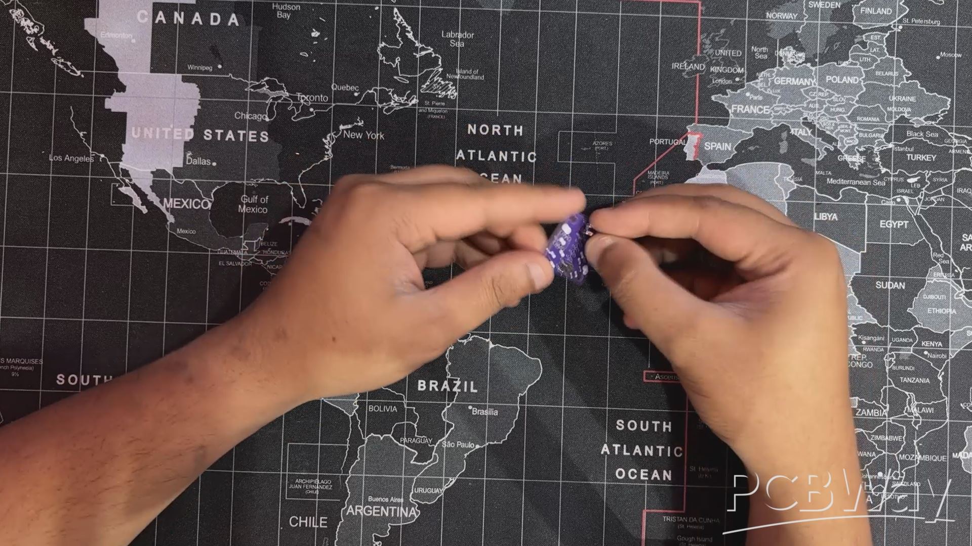
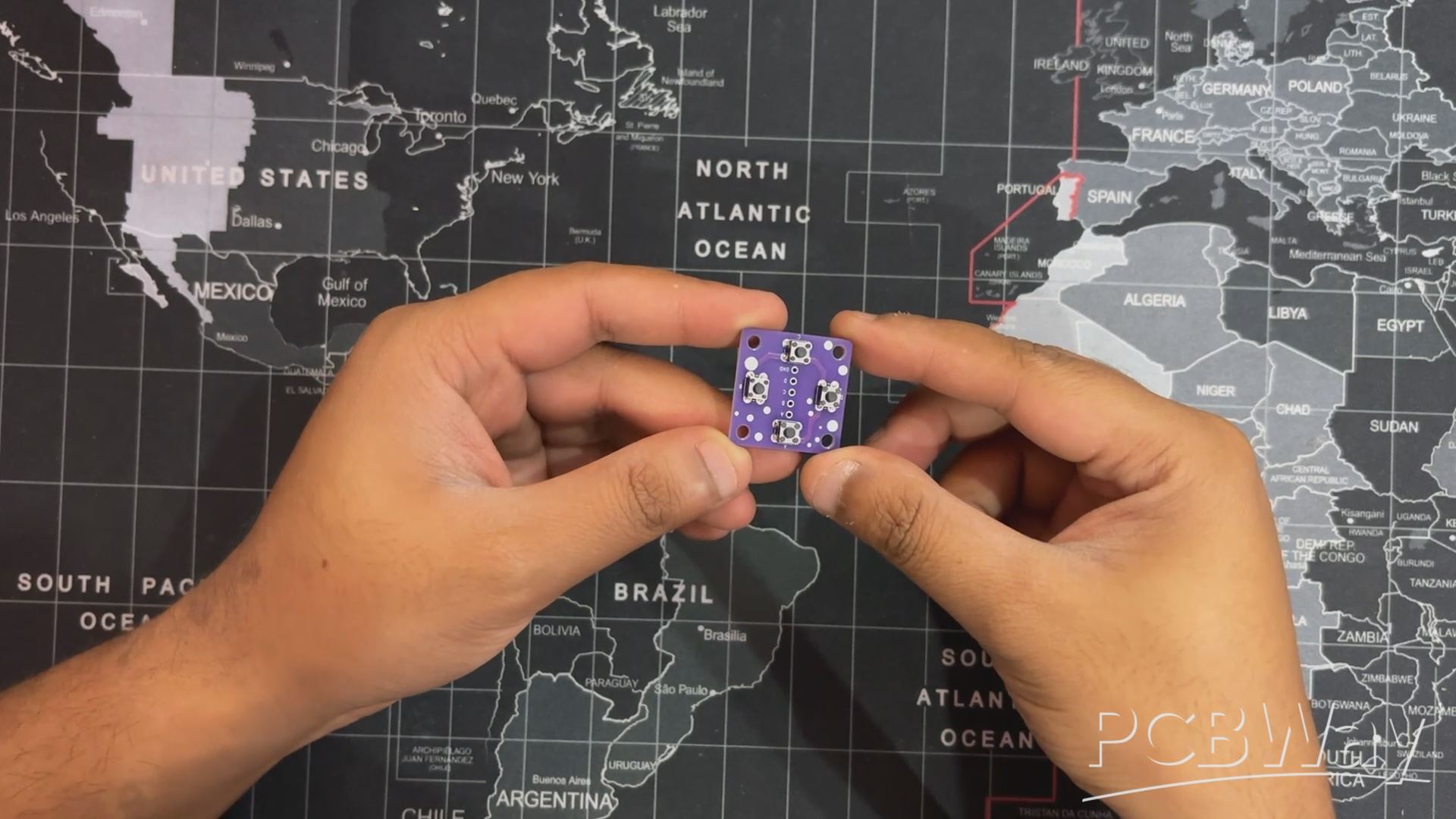
- Button board assembly was pretty straightforward. We start by placing all switches in their position.
- Next, we flipped the board over and then used a soldering iron to solder all the leads of the push buttons.
- The switch PCB is now assembled.
HARDWARE: WAVSHARE ESP32 P4 WIFI6 Touch LCD
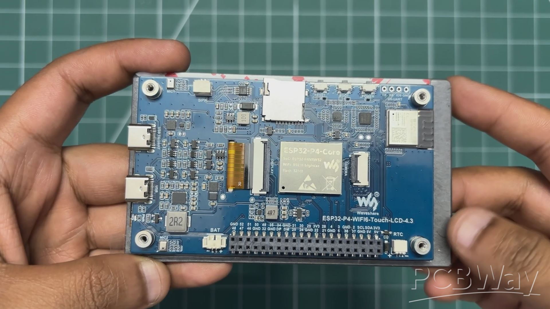
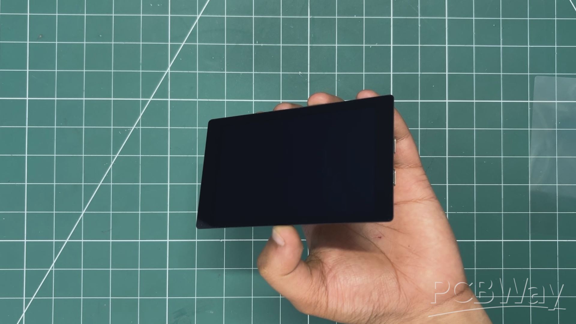
Here's the star of our project: the Waveshare ESP32-P4 Development Board. It is built around the ESP32-P4 microcontroller, featuring a dual-core 400 MHz RISC-V processor for high-performance applications, along with a dedicated low-power RISC-V core for efficient background tasks.
The board comes equipped with a 4.3-inch IPS capacitive touch display with a resolution of 480 × 800 pixels, providing a responsive and vibrant user interface. It supports a rich set of human-machine interaction peripherals, including a MIPI-CSI camera interface with an integrated Image Signal Processor (ISP) for image capture and processing applications. The board also features USB 2.0 OTG High-Speed (HS) support, enabling fast data transfer and versatile USB connectivity options.
For hardware expansion, it includes an onboard 40-pin GPIO header that is compatible with selected Raspberry Pi HAT expansion boards, making it easy to integrate additional sensors, modules, and peripherals.
An additional highlight of this development board is the onboard ESP32-C6-MINI module. Since the ESP32-P4 itself does not include native Wi-Fi or Bluetooth connectivity, the ESP32-C6 serves as a dedicated wireless coprocessor, providing Wi-Fi 6 (802.11ax) and Bluetooth Low Energy (BLE 5.x) capabilities. This combination allows developers to leverage the processing power of the ESP32-P4 while maintaining modern wireless connectivity for IoT and connected-device applications.
You can check out more details about this board from Wavshare's WIKI PAGE.
https://docs.waveshare.com/ESP32-P4-WIFI6-Touch-LCD-4.3
ESP32 P4 WIFI6 Touch LCD SPEAKER ASSEMBLY
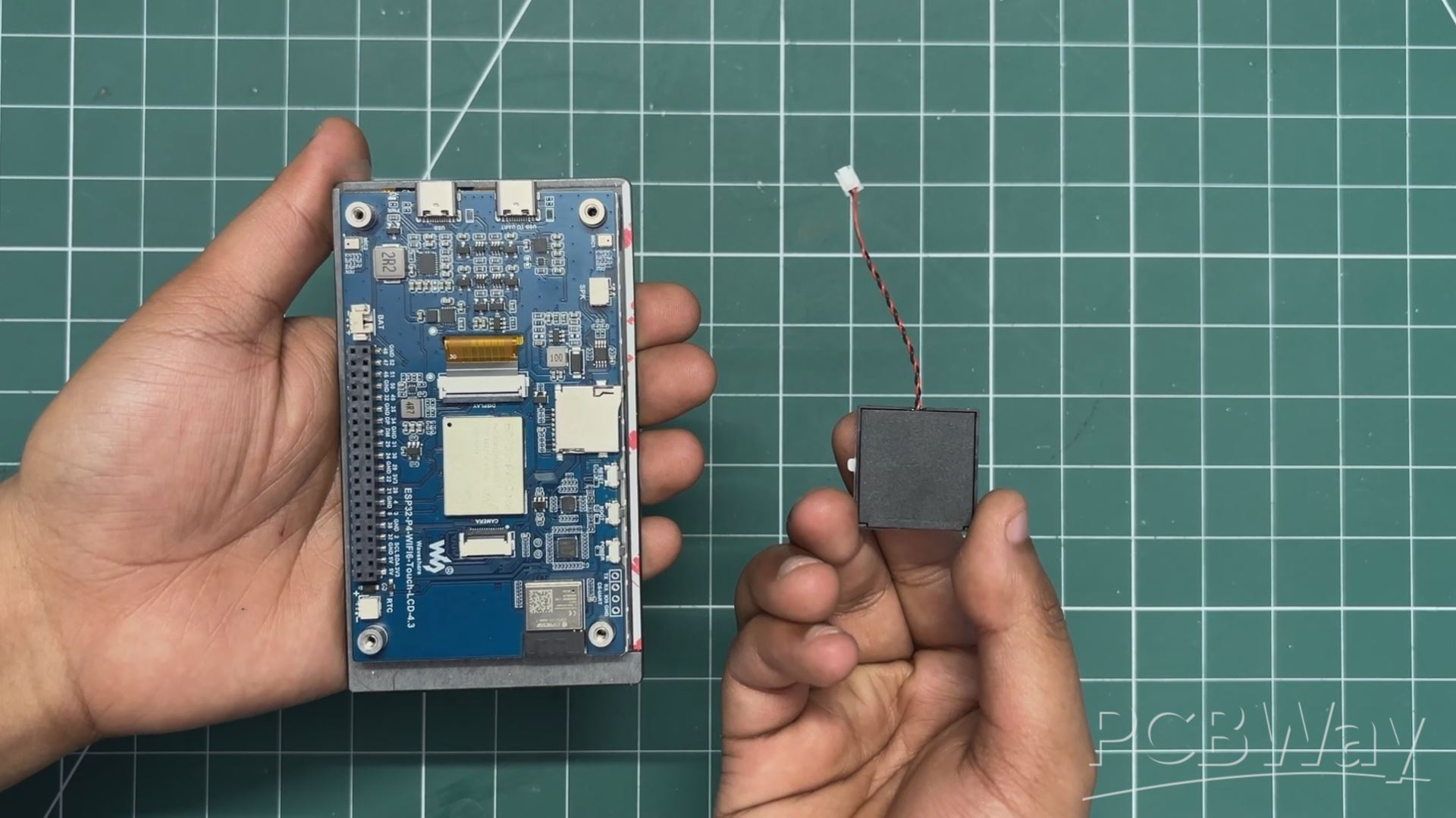
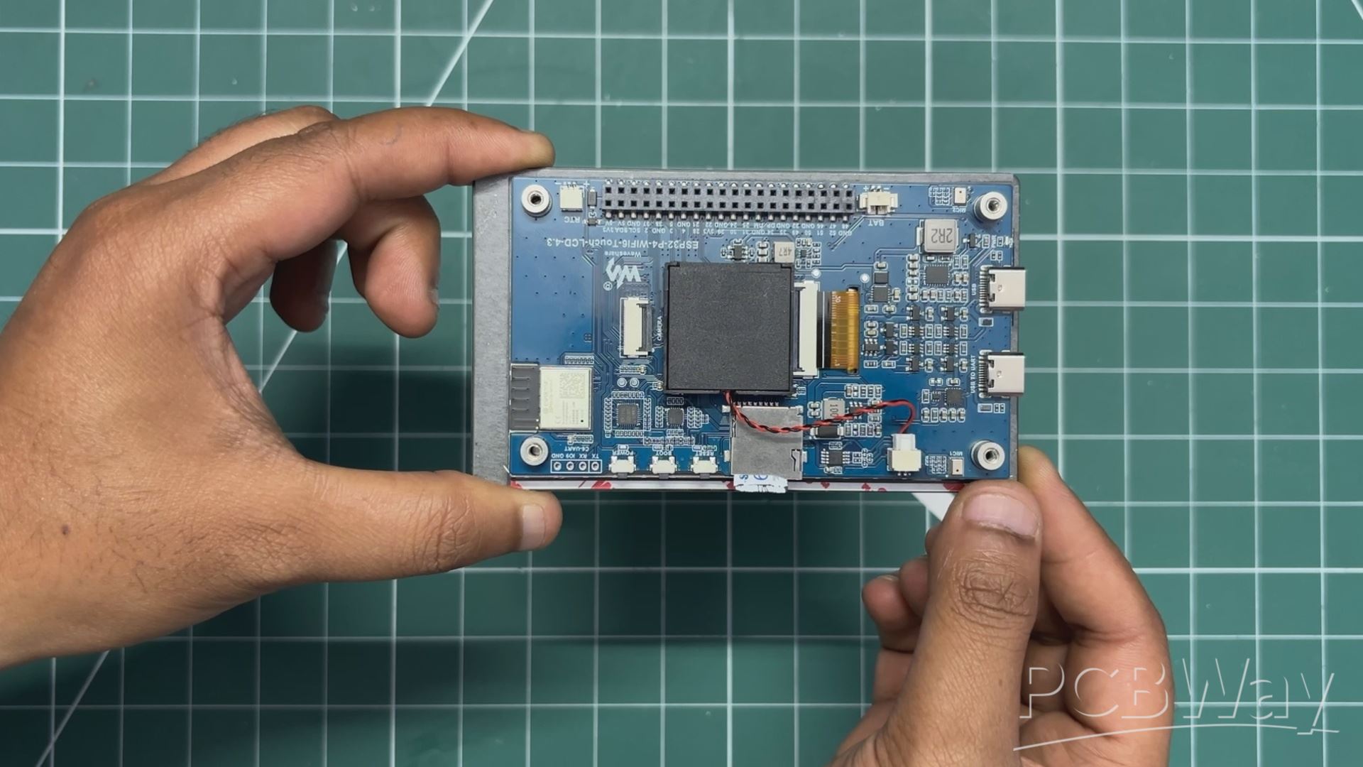
- In the Waveshare ESP32-P4 Wi-Fi 6 Touch LCD Kit, an onboard compatible speaker is included.
- This speaker serves as a crucial component of our build, as it will be used to output the various astromech sound effects generated by the system.
- To install the speaker, we first removed the protective layer from the 3M double-sided adhesive tape attached to its back.
- The speaker was then carefully positioned in the center of the board, directly above the ESP32-P4 metal shielding can, ensuring that it did not interfere with any connectors or components.
- Once aligned correctly, the speaker was pressed firmly into place, securing it to the board and completing the installation.
GREEBLES PART ASSEMBLY
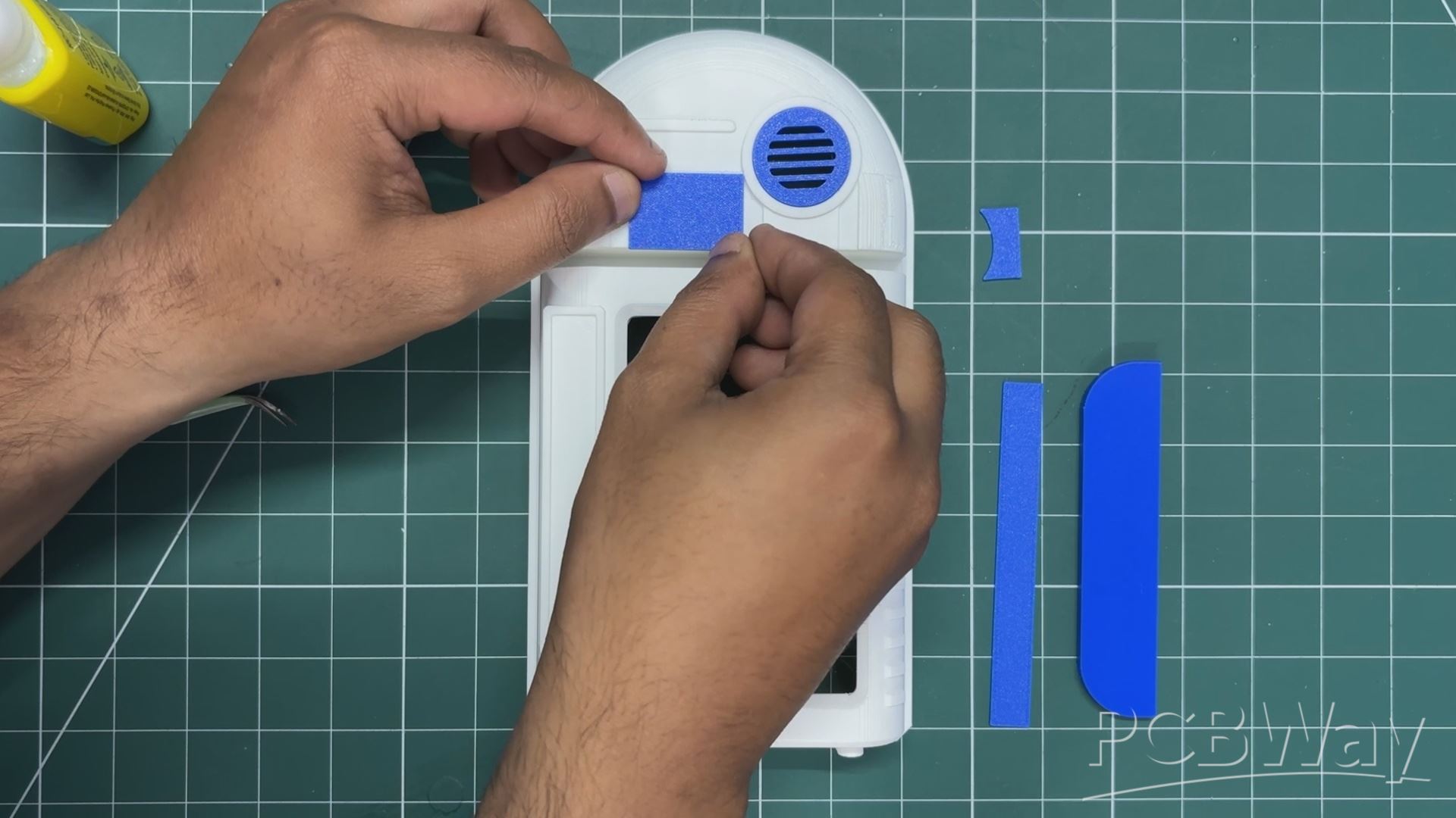
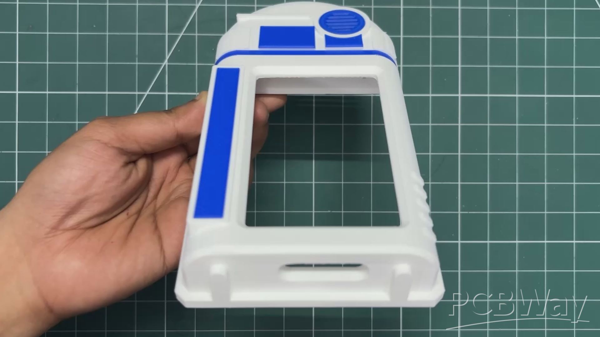
- We start the greebles assembly process by placing the Grill part in its position first. It is pressed firmly into place and gets locked in position due to the zero surface clearance.
- Next, we apply super glue to the mounting positions of the other greeble parts, then position them one by one.
- All parts require some super glue for mounting.
ESP32 P4 & SWITCH BOARD ASSEMBLY
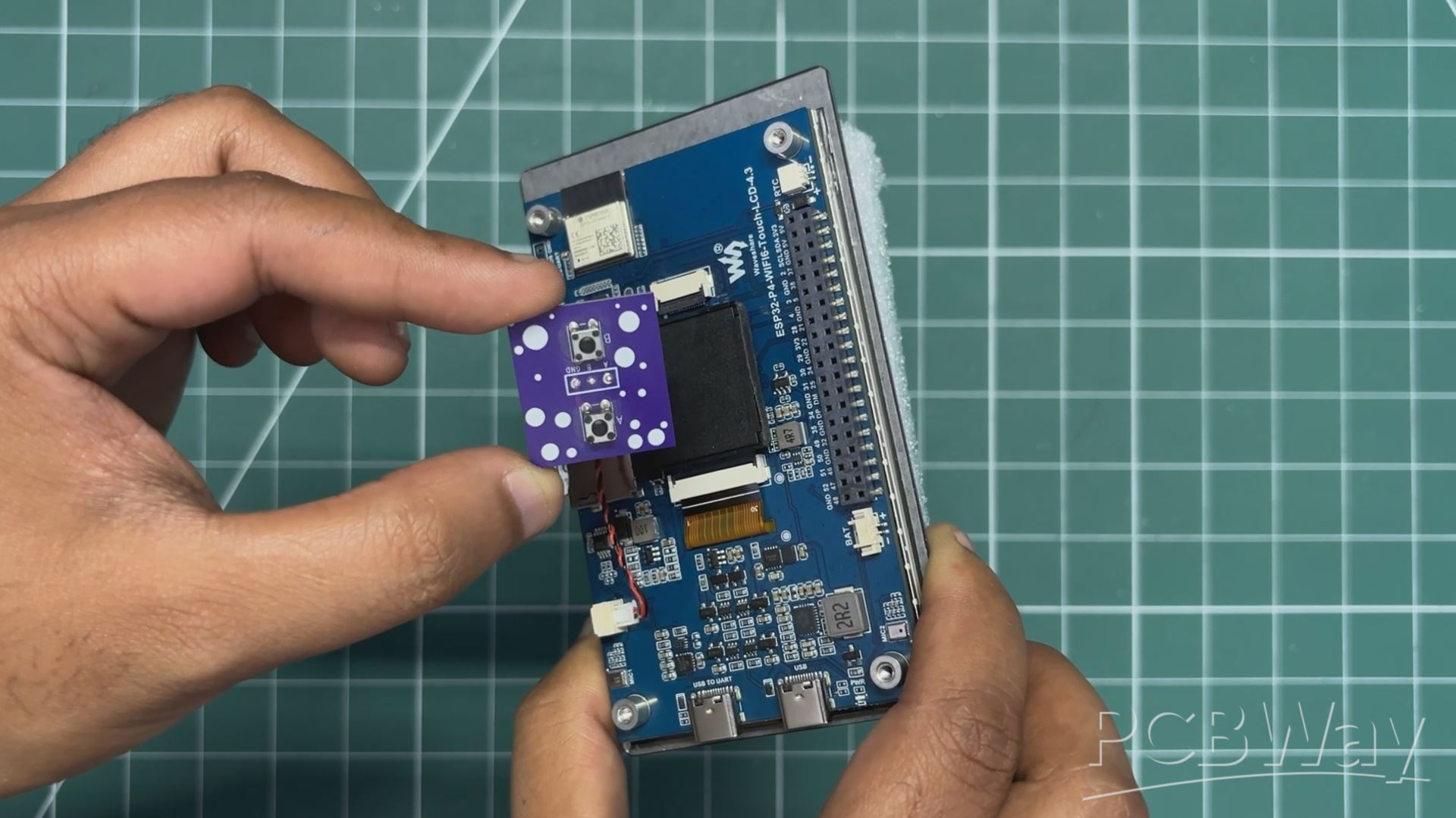
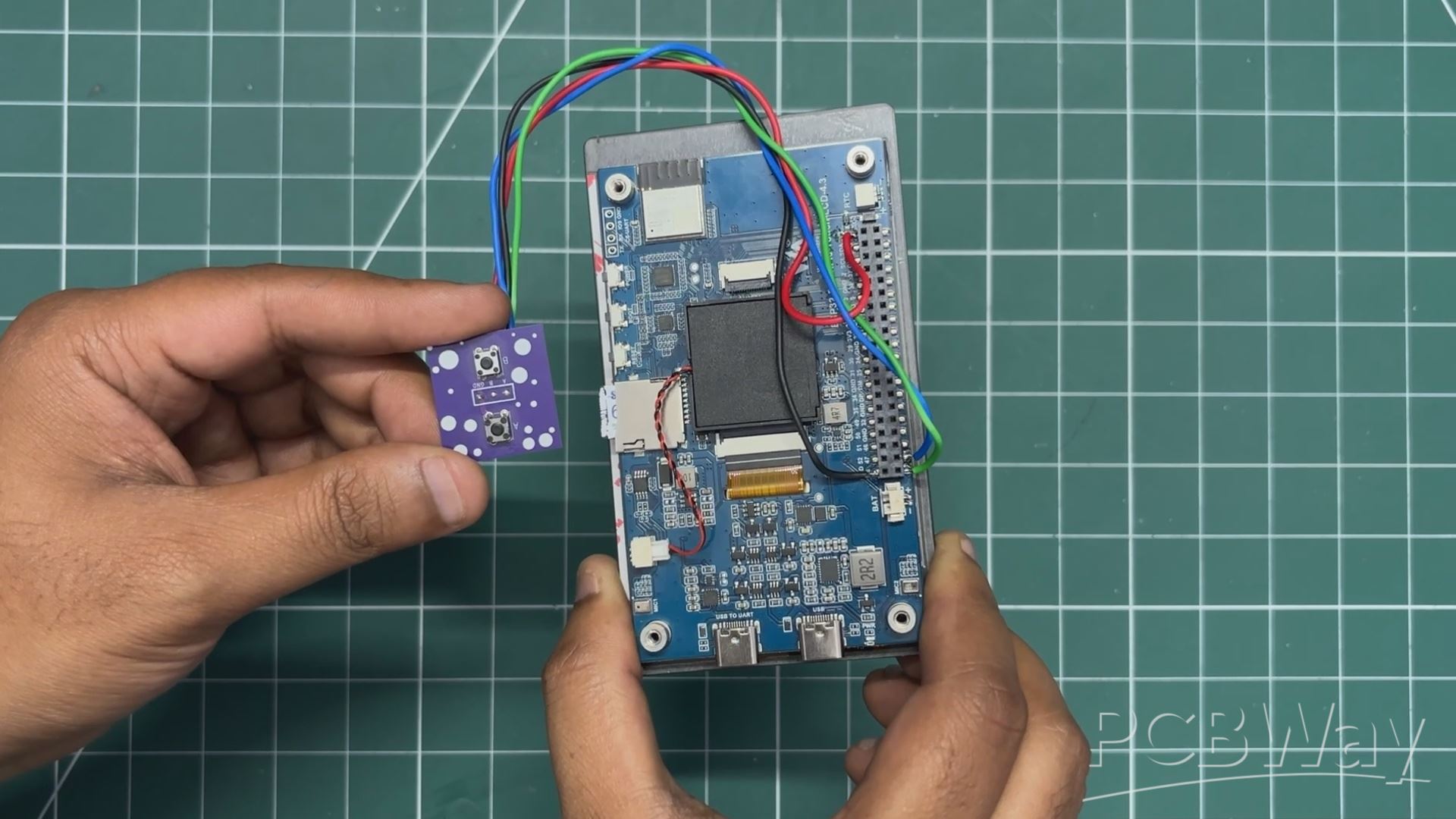
- Next, we connect our Switch Board to the ESP32-P4 Board.
- We connect the GND pin of the Switch Board to the GND pin of the ESP32-P4, GPIO48 to Button 1, and GPIO47 to Button 2.
- For these connections, single-core silver-plated copper wire is used.
SWITCH SECTION ASSEMBLY
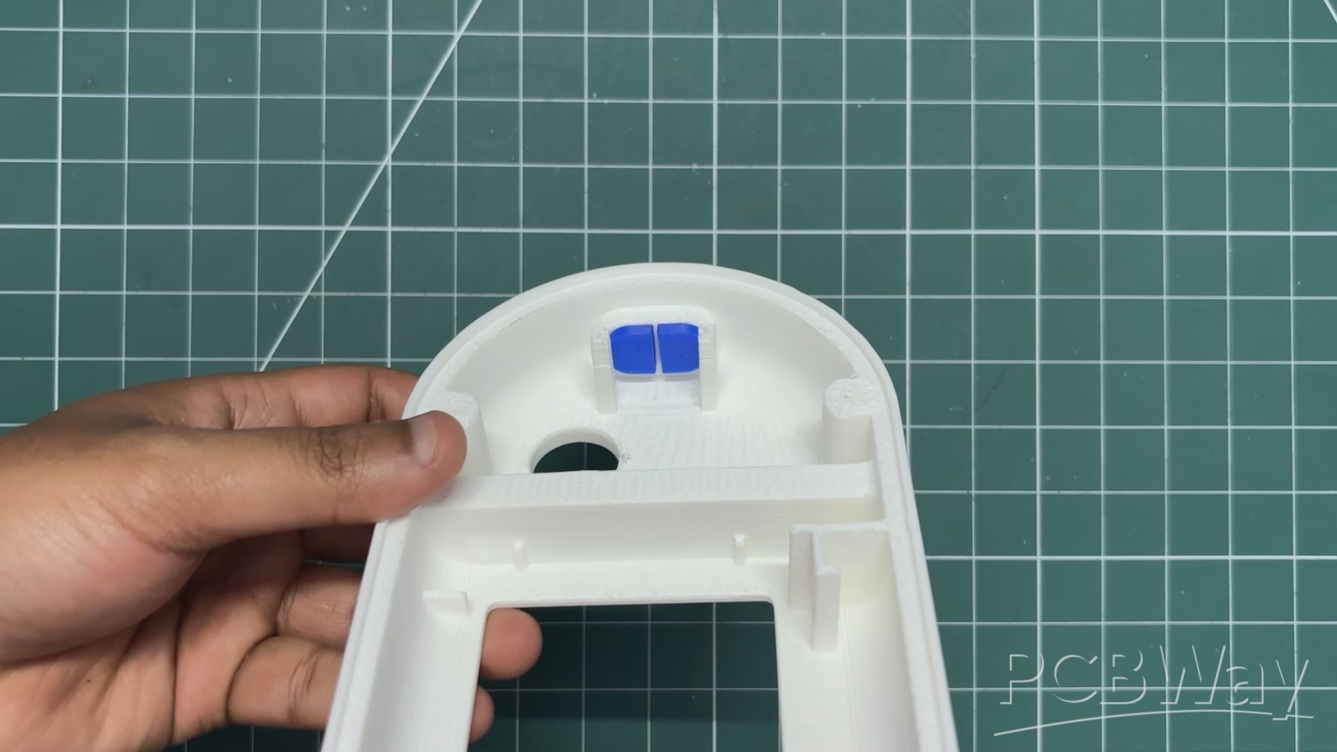
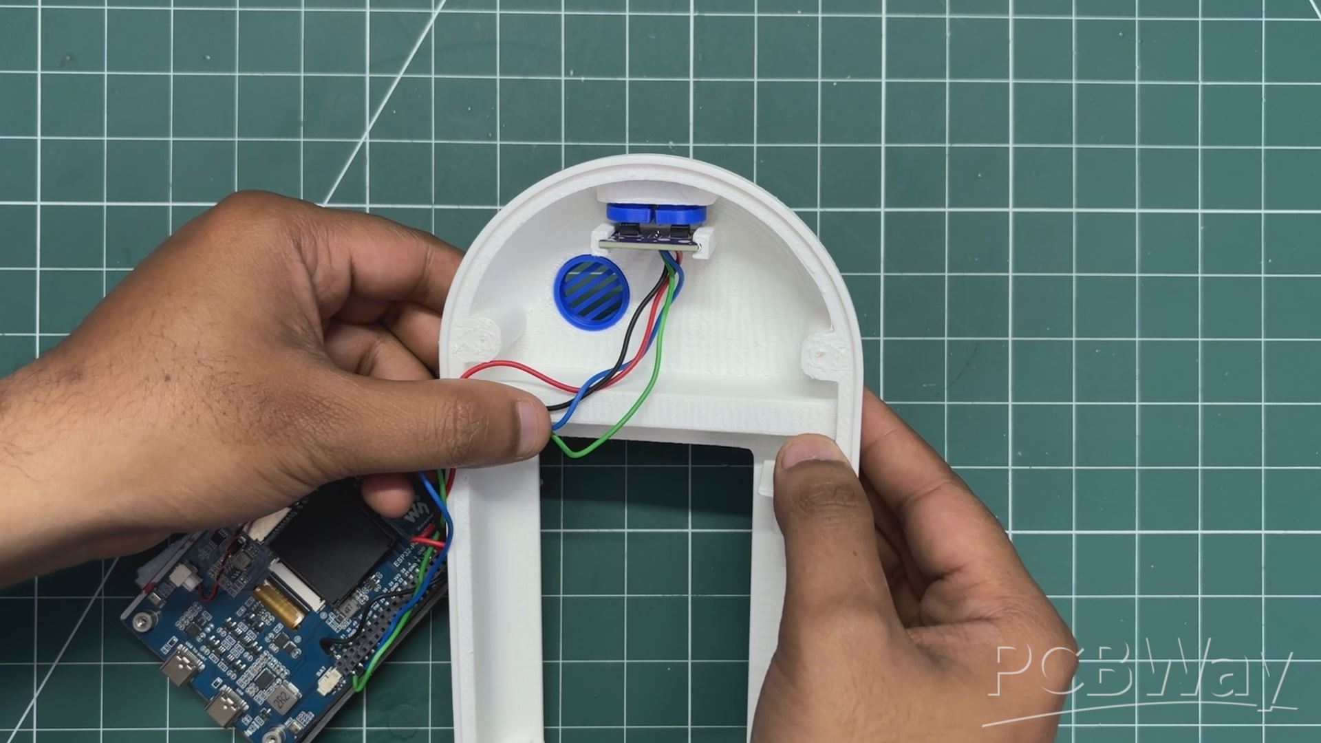
- The 3D-printed switch actuators were positioned in place from inside the main enclosure.
- Next, the switch PCB is slid into position slightly below the switch actuators. It is pressure-fitted in place and remains securely fixed.
ESP32 P4 ASSEMBLY
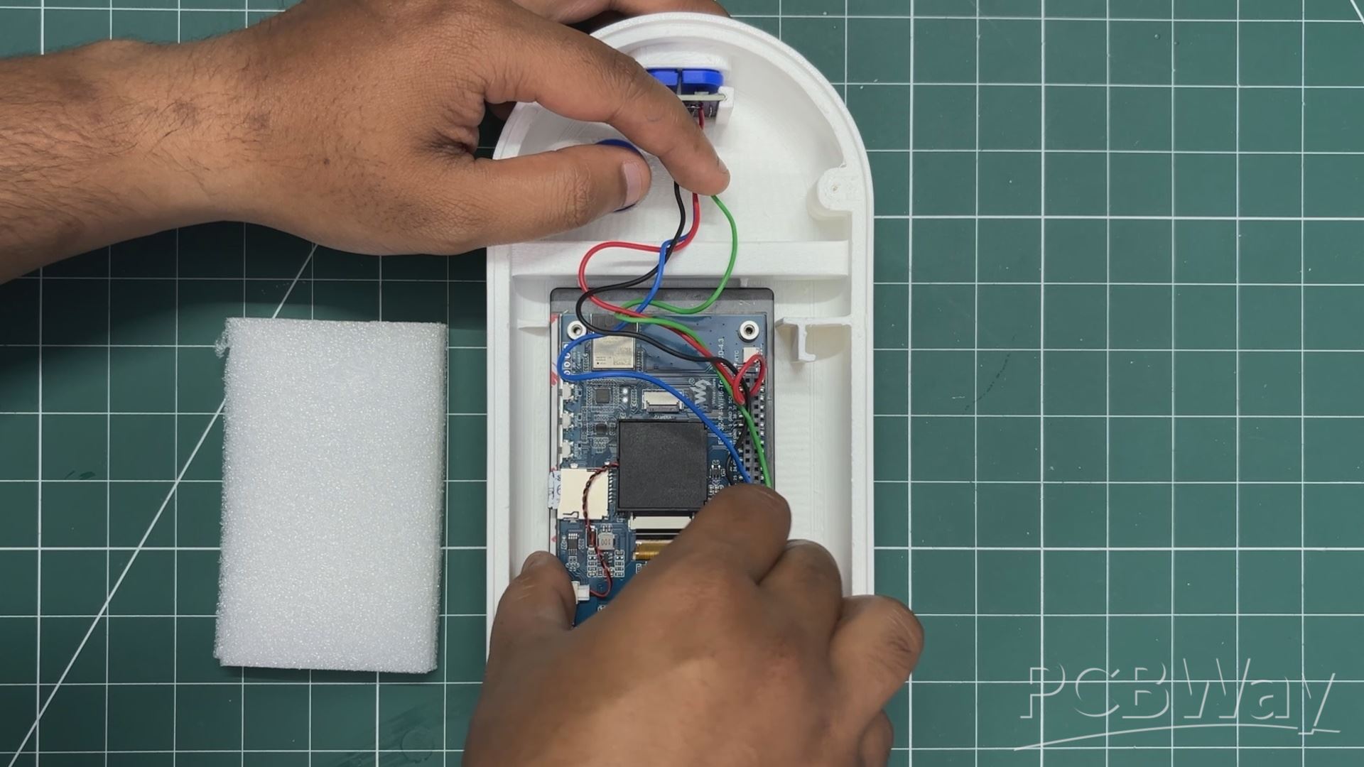
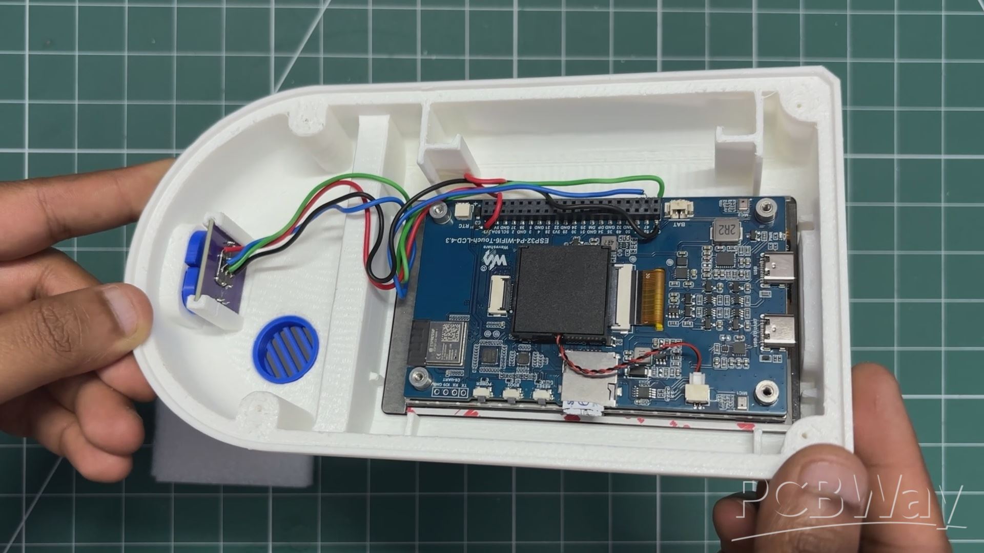
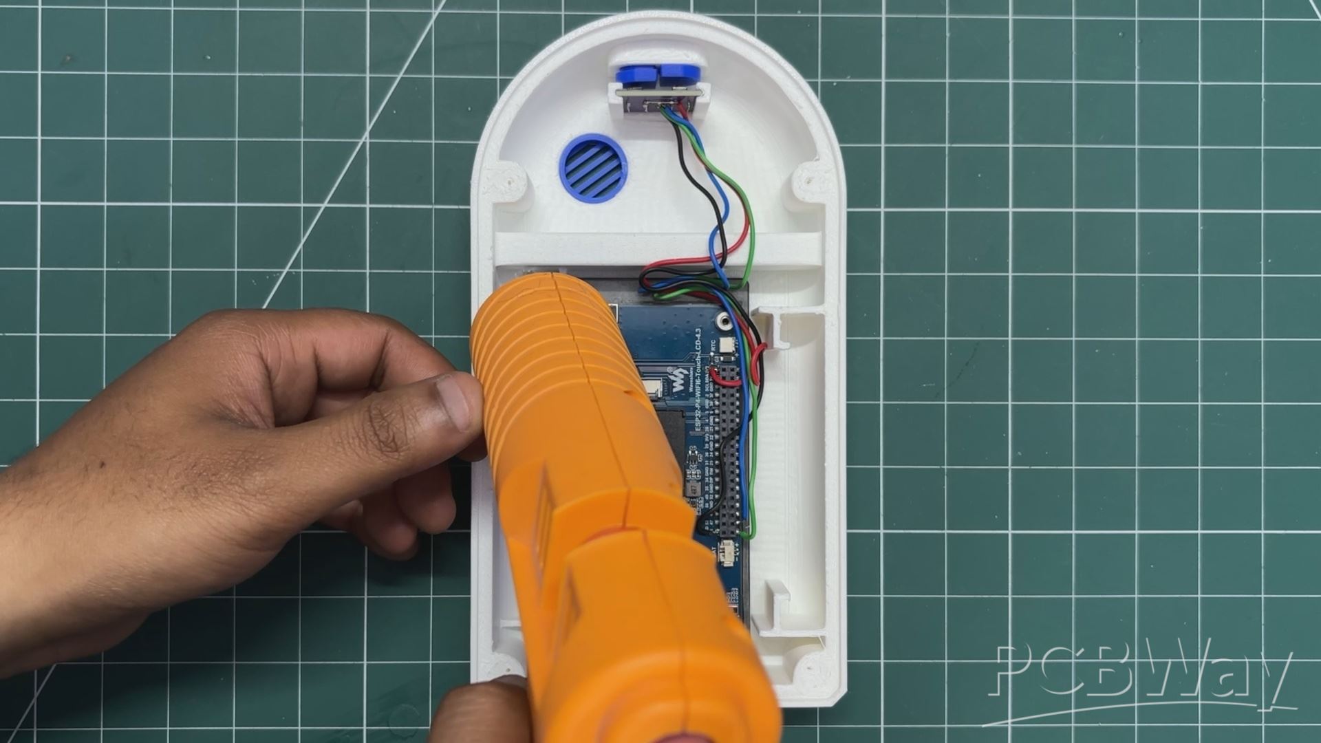
- The ESP32-P4 board is placed into position from the inside of the main enclosure. To secure it in place, hot glue is applied around all four corners of the display, firmly attaching it to the 3D-printed enclosure.
- I've been watching James's channel a lot recently, and I really like how he uses hot glue in many of his builds instead of overengineering screw bosses, brackets, and retainers just to hold a part in place. For non-load-bearing components, it's a simple, fast, and surprisingly effective solution.
POWER SOURCE ASSEMBLY
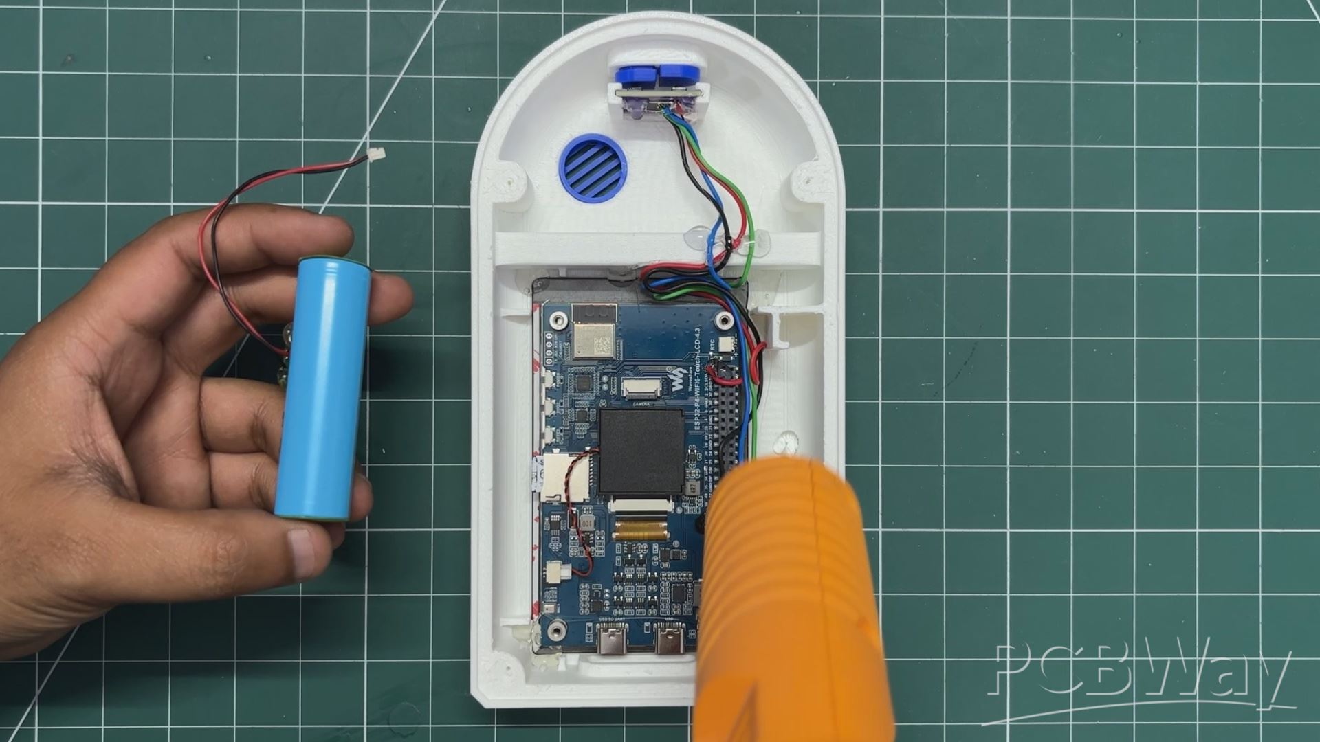
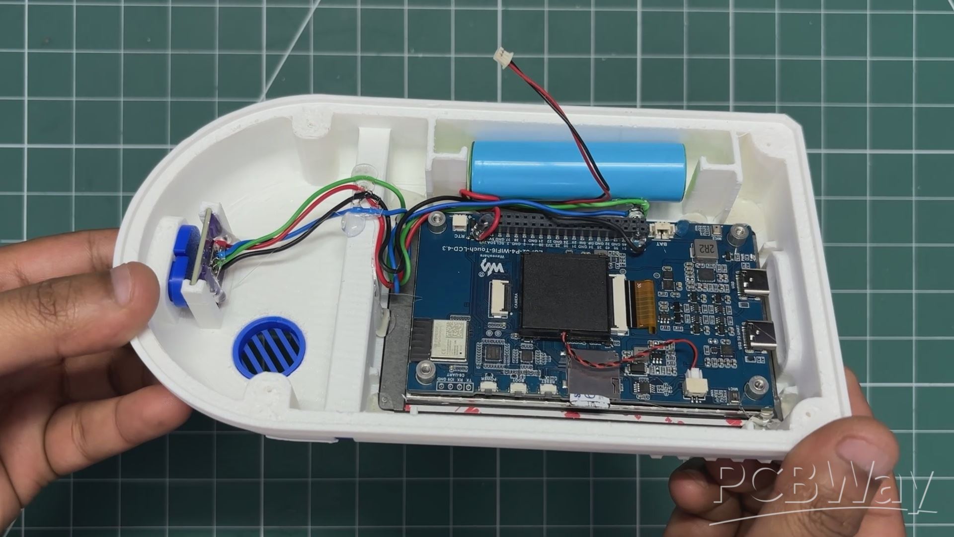
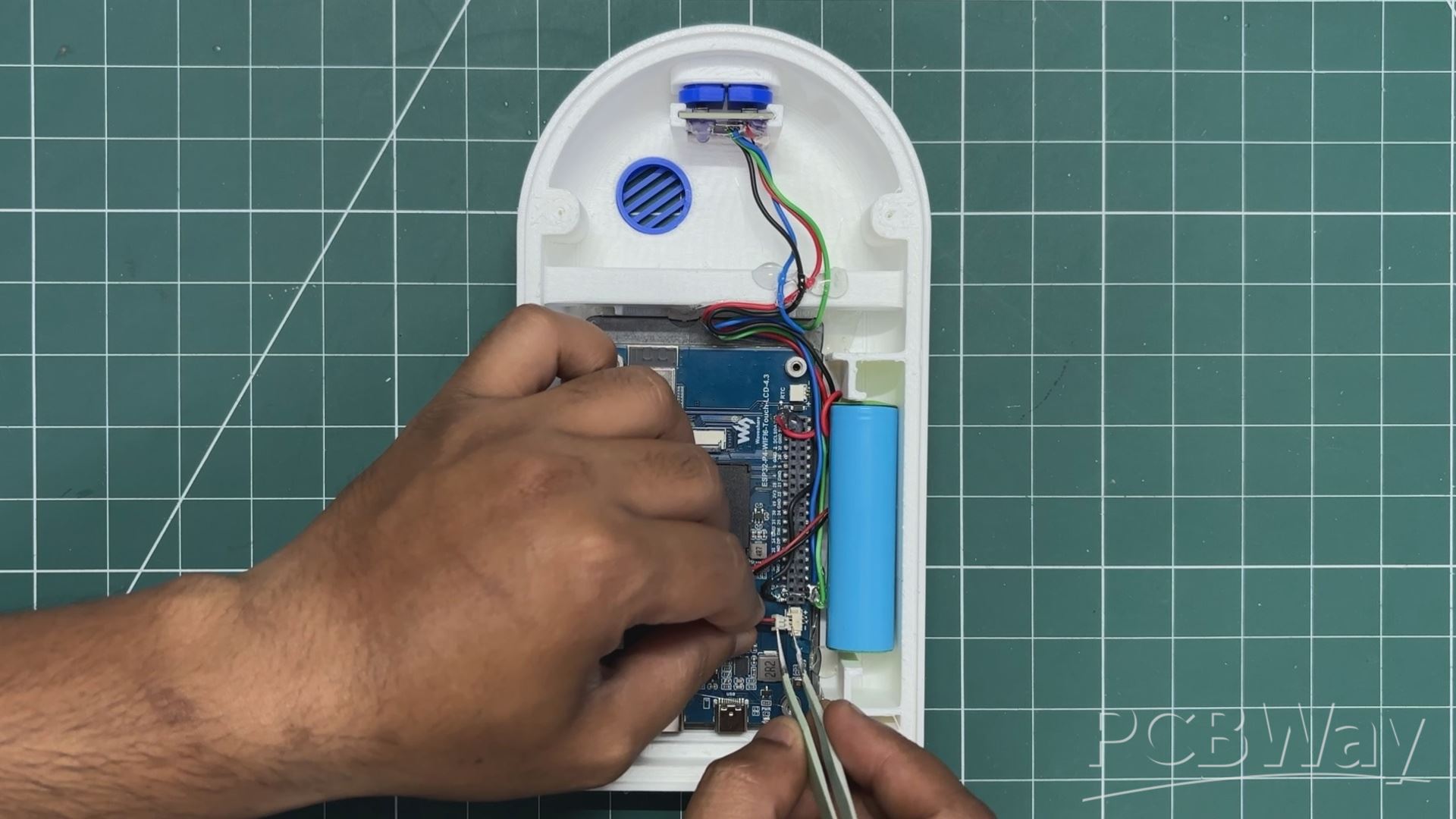
- For the power source, I am using a standard 3.7 V, 2200 mAh 18650 lithium-ion cell. A JST connector has been added to the battery, making it compatible with the ESP32-P4 board's battery connector.
- A small amount of hot glue is applied to the battery mounting area, and the cell is placed on top of it. Once the glue hardens, the battery is securely held in position.
- Finally, using a pair of tweezers, the JST connector from the battery is plugged into the ESP32-P4 board's battery connector, completing the internal power setup.
FINAL ASSEMBLY
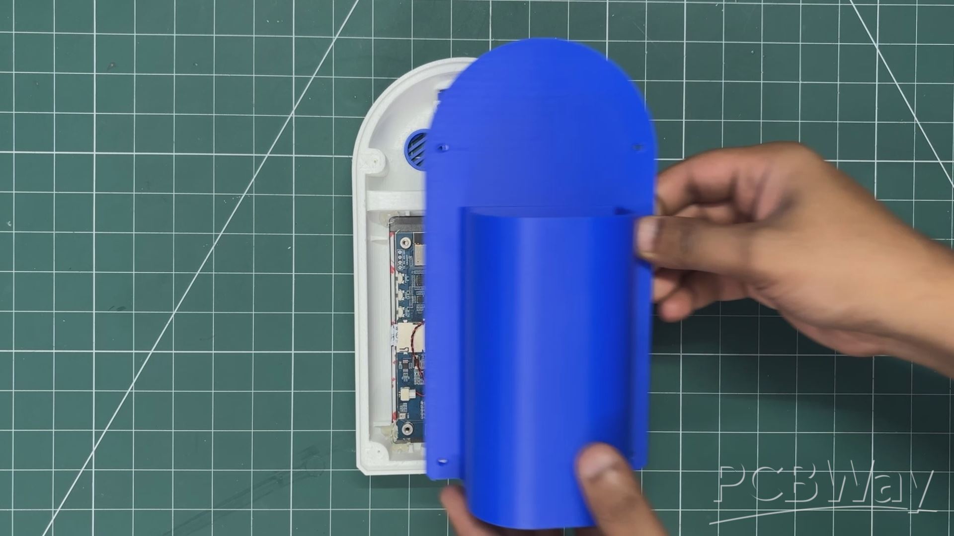
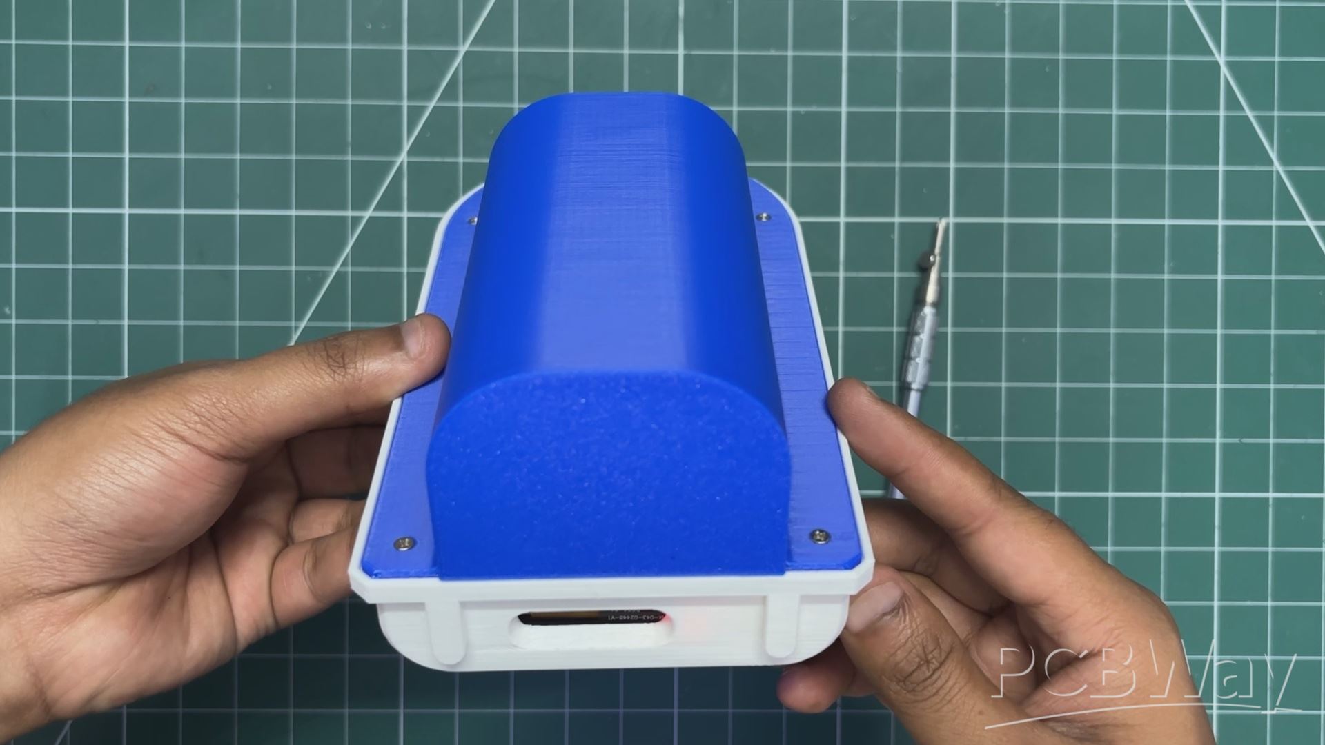
Finally, the back lid is placed in position, and four M2 screws are used to secure both enclosure parts together, completing the assembly process.
CODE
The code for this project was done in collaboration with Aahan Sharma; he took care of the whole code part.
Full code can be found here on his GitHub page: https://github.com/AahanDoesGit/r2d2
While trying to build this project, I struggled to get the ESPIDF VS Code extension working properly on my MacBook. The paths and Python environments can sometimes get tangled. I found that setting up ESP-IDF purely via the macOS Terminal is much cleaner
RESULT
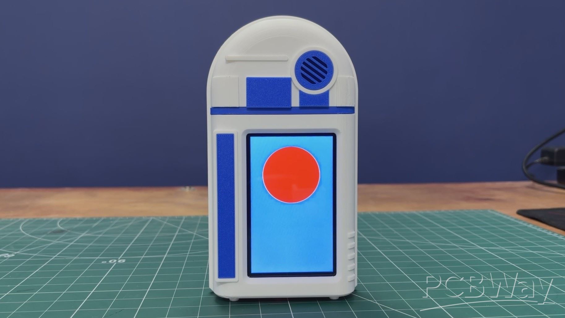
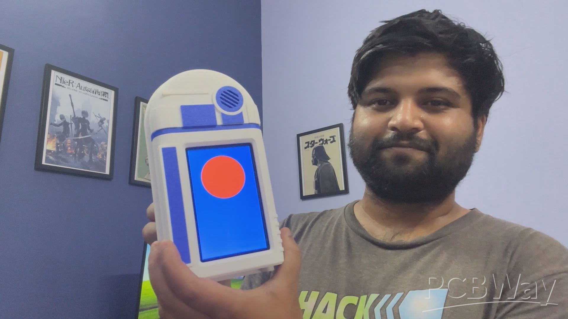
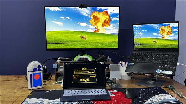
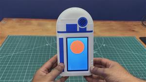
And here is the final result: a fully functional, talking R2-D2-themed desk bot that doubles as a handy pen holder.
You can store your pens and stuff on the back while the droid keeps you company at your desk. The front screen displays a striking blue background with a red circle that symbolizes R2-D2’s eye, which pulses and animates whenever the droid speaks. It’s the perfect blend of utility and personality, a true desk companion that feels like it’s come to life right in front of you.
Every 20 seconds, the device plays a 5-second sequence of random astromech beeps and chirps. Instead of playing static files, it uses math to pick random frequencies and then bends the pitch up and down in real time. Because of this randomness, the sounds feel just as organic and unpredictable as a real droid would make.
For manual control, I’ve mapped two buttons that do the following functions:
Button 1 triggers our Easter Egg songs. I coded these six special tracks purely using R2-D2’s beep frequencies. The library includes AC/DC’s Back in Black (R2-D2 Edition), Happy Birthday, Rick Astley’s Never Gonna Give You Up (Rickroll!), the Star Wars Main Theme, the Super Mario Bros. Theme, and my personal favorite, the Pokémon Diamond/Pearl Lake Theme.
Button 2 acts as a physical toggle for the screen mode. Even if you don't have the web dashboard open, you can press this button to switch the display back and forth between the Radar UI and GIF play modes.
For now, this project has been completed. Special thanks for reaching this far, and I’ll be back with a new project very soon.
Stationery Unit D2
Project images are for reference only. Actual production is based on the manufacturing files on the project page.
Please review the designer's notes (e.g., PCB thickness) and select the appropriate options.
PCBWay is not responsible
for issues caused by unsuitable parameter selections.
For more important ordering information, please refer to
Read More









Raspberry Pi 5 7 Inch Touch Screen IPS 1024x600 HD LCD HDMI-compatible Display for RPI 4B 3B+ OPI 5 AIDA64 PC Secondary Screen(Without Speaker)
BUY NOW


- Comments(1)
- Likes(0)
More by Arnov Arnov sharma
-
 Poké Pi - Cyberdeck
Greetings everyone, and welcome back!Meet Poke Pi, a DIY Raspberry Pi-based gaming console themed ar...
Poké Pi - Cyberdeck
Greetings everyone, and welcome back!Meet Poke Pi, a DIY Raspberry Pi-based gaming console themed ar...
-
 Wireless Game Controller V1
Greetings everyone and welcome back.This is my prototype for a wireless Bluetooth game controller bu...
Wireless Game Controller V1
Greetings everyone and welcome back.This is my prototype for a wireless Bluetooth game controller bu...
-
 DIY XBOX Controller
Greetings everyone, and welcome back. Here's something fun and custom.This is my version of an Xbox ...
DIY XBOX Controller
Greetings everyone, and welcome back. Here's something fun and custom.This is my version of an Xbox ...
-
 Pocket SNES
Greetings everyone, and welcome back! Today, I’ve got something fun and tiny to share—the Pocket SNE...
Pocket SNES
Greetings everyone, and welcome back! Today, I’ve got something fun and tiny to share—the Pocket SNE...
-
 Batocera Arcade Box
Greetings everyone and welcome back, Here's something. Fun and nostalgic. Right now, we are using ou...
Batocera Arcade Box
Greetings everyone and welcome back, Here's something. Fun and nostalgic. Right now, we are using ou...
-
 64x32 Matrix Panel Setup with PICO 2
Greetings everyone and welcome back.So here's something fun and useful: a Raspberry Pi Pico 2-powere...
64x32 Matrix Panel Setup with PICO 2
Greetings everyone and welcome back.So here's something fun and useful: a Raspberry Pi Pico 2-powere...
-
 Portable Air Quality Meter
Hello everyone, and welcome back! Today, I have something incredibly useful for you—a Portable Air Q...
Portable Air Quality Meter
Hello everyone, and welcome back! Today, I have something incredibly useful for you—a Portable Air Q...
-
 WALKPi PCB Version
Greetings everyone and welcome back, This is the WalkPi, a homebrew audio player that plays music fr...
WALKPi PCB Version
Greetings everyone and welcome back, This is the WalkPi, a homebrew audio player that plays music fr...
-
 Delete Button XL
Greetings everyone and welcome back, and here's something fun and useful.In essence, the Delete Butt...
Delete Button XL
Greetings everyone and welcome back, and here's something fun and useful.In essence, the Delete Butt...
-
 Arduino Retro Game Controller
Greetings everyone and welcome back. Here's something fun.The Arduino Retro Game Controller was buil...
Arduino Retro Game Controller
Greetings everyone and welcome back. Here's something fun.The Arduino Retro Game Controller was buil...
-
 Super Power Buck Converter
Greetings everyone and welcome back!Here's something powerful, The SUPER POWER BUCK CONVERTER BOARD ...
Super Power Buck Converter
Greetings everyone and welcome back!Here's something powerful, The SUPER POWER BUCK CONVERTER BOARD ...
-
 Pocket Temp Meter
Greetings and welcome back.So here's something portable and useful: the Pocket TEMP Meter project.As...
Pocket Temp Meter
Greetings and welcome back.So here's something portable and useful: the Pocket TEMP Meter project.As...
-
 Pico Powered DC Fan Driver
Hello everyone and welcome back.So here's something cool: a 5V to 12V DC motor driver based around a...
Pico Powered DC Fan Driver
Hello everyone and welcome back.So here's something cool: a 5V to 12V DC motor driver based around a...
-
 Mini Solar Light Project with a Twist
Greetings.This is the Cube Light, a Small and compact cube-shaped emergency solar light that boasts ...
Mini Solar Light Project with a Twist
Greetings.This is the Cube Light, a Small and compact cube-shaped emergency solar light that boasts ...
-
 PALPi V5 Handheld Retro Game Console
Hey, Guys what's up?So this is PALPi which is a Raspberry Pi Zero W Based Handheld Retro Game Consol...
PALPi V5 Handheld Retro Game Console
Hey, Guys what's up?So this is PALPi which is a Raspberry Pi Zero W Based Handheld Retro Game Consol...
-
 DIY Thermometer with TTGO T Display and DS18B20
Greetings.So this is the DIY Thermometer made entirely from scratch using a TTGO T display board and...
DIY Thermometer with TTGO T Display and DS18B20
Greetings.So this is the DIY Thermometer made entirely from scratch using a TTGO T display board and...
-
 Motion Trigger Circuit with and without Microcontroller
GreetingsHere's a tutorial on how to use an HC-SR505 PIR Module with and without a microcontroller t...
Motion Trigger Circuit with and without Microcontroller
GreetingsHere's a tutorial on how to use an HC-SR505 PIR Module with and without a microcontroller t...
-
 Motor Driver Board Atmega328PU and HC01
Hey, what's up folks here's something super cool and useful if you're making a basic Robot Setup, A ...
Motor Driver Board Atmega328PU and HC01
Hey, what's up folks here's something super cool and useful if you're making a basic Robot Setup, A ...
-
SmallOLED - Live PC Stats, Animated Clocks & Audio Visualizer
671 0 3 -
"Talking Multimeter": Arduino-Based Speech Add-on for Multimeters with SCPI Protocol
381 0 1 -
Programmable Mist Maker - XIAO / QT PY Extension
2821 2 3 -
RadioHAT - Raspberry Pi radio development platform
2420 0 4 -
-
-
-
ARPS-2 – Arduino-Compatible Robot Project Shield for Arduino UNO
4505 0 6














