Solar Communication: Low-Cost Offline Data Through Light
PROJECT OVERVIEW
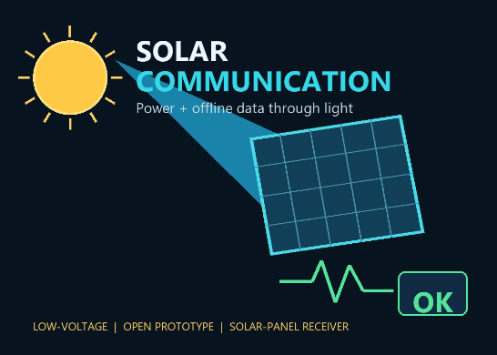
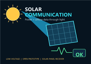
Solar Communication is a low-voltage visible-light communication experiment that uses a small photovoltaic panel as the optical receiver. A transmitter modulates an LED with digital data. The solar panel converts the changing photon flux into a changing electrical signal while its average DC output remains available for energy harvesting. The project is designed as an inexpensive offline sensor/status link, not as a replacement for the global internet.
WHAT WORKS
Photovoltaic cells already convert light into electrical current. When LED brightness changes, the panel current changes too. The receiver separates the small AC communication component from the larger DC illumination component. AC coupling, amplification, hysteresis, packet framing, and checksum validation make the signal usable. A dedicated photodiode is faster, but a small solar panel is practical for low-rate demonstrations and can provide energy at the same time.
SYSTEM ARCHITECTURE
Transmitter:
1. A microcontroller creates a packet containing a preamble, version, payload length, sequence number, payload, and checksum or CRC.
2. A logic-level MOSFET switches a low-voltage diffused LED or regulated LED module.
3. On-off keying is the simplest modulation. Manchester coding may be used for regular timing transitions.
Optical channel:
4. Visible or infrared photons carry the encoded brightness changes across free space.
5. Range and reliability depend on LED optical power, alignment, ambient light, panel area, panel capacitance, and symbol rate.
Receiver:
6. The solar panel produces DC power plus a smaller AC data component.
7. A coupling capacitor blocks the steady DC level.
8. A midpoint-bias network keeps the AC waveform inside the single-supply amplifier range.
9. A low-noise op-amp increases signal amplitude.
10. A comparator with hysteresis restores clean digital transitions.
11. A receiver microcontroller searches for the preamble, reads the declared payload, checks timing, and validates the checksum.
12. The output displays OK only after the complete packet passes validation.
ENERGY AND DATA SEPARATION
The panel output can be divided into three branches. The energy branch uses reverse-current protection and a solar power-management circuit matched to the storage chemistry. The data branch uses AC coupling, amplification, and a comparator. The measurement branch records panel voltage, current, signal amplitude, noise, and packet success rate. Initial communication tests should omit battery charging and power both electronics from isolated USB power banks.
FIRST PROTOTYPE TARGET
Start at 10 to 100 symbols per second using the text SOLAR OK. Transmit the packet 100 times across approximately one metre under stable indoor lighting. Count a packet as successful only when the preamble, length, timing, sequence, and checksum all pass. The initial target is at least 95 valid packets with zero false-OK results. Repeat under changed ambient light without manually retuning the receiver.
TEST PLAN
Stage A: Observe solar-panel voltage changing when a flashlight turns on and off.
Stage B: Drive the LED with a slow square wave and observe the received waveform.
Stage C: Add AC coupling and confirm steady illumination is rejected.
Stage D: Add amplification and comparator hysteresis.
Stage E: Decode a repeating 1010 pattern before sending text.
Stage F: Add packets, sequence numbers, and CRC/checksum.
Stage G: Measure packet success rate, bit error rate, false-OK rate, signal-to-noise ratio, harvested power, and energy per valid bit.
Stage H: Sweep distance, angle, lighting, and symbol rate one variable at a time.
EXPECTED COST
A reuse-first test can cost about USD 10-20 when a flashlight, controller, breadboard, and measuring tools are already available. A basic digital link is approximately USD 25-45 using inexpensive compatible controller boards. A documented-brand version is roughly USD 45-80. Adding a suitable solar power manager and protected storage can bring the total to approximately USD 60-120. Prices vary by supplier and date.
PCB DIRECTION
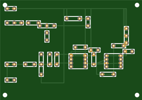
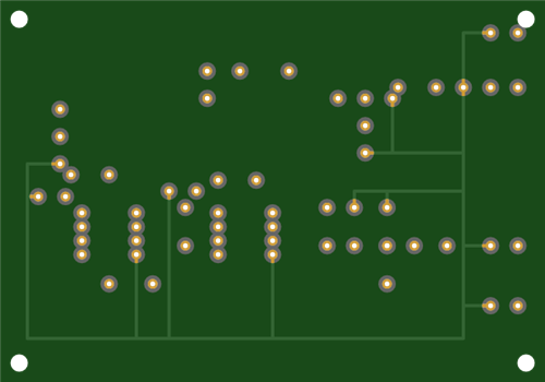
The eventual design can use two simple boards. The transmitter board contains the controller connector, MOSFET LED driver, current-limiting components, status LED, test points, and power protection. The receiver board contains the solar-panel connector, selectable AC-coupling network, midpoint reference, two-stage gain or op-amp/comparator chain, hysteresis, controller connector, test points, and a physically separate optional energy-harvesting output. Power and sensitive analog return paths should be separated and joined deliberately. Decoupling capacitors should be placed close to each active device. The prototype should provide gain and threshold options because panel size and ambient light vary.
OFFLINE NETWORK USE
Decoded packets can enter an offline PC over USB serial. The PC can host a local website and database containing simulations, documents, sensor logs, and ALLOW/REVIEW/BLOCK safety results. Multiple solar optical nodes can use device identifiers and time slots. A checksum detects accidental corruption; authenticated commands require a keyed message-authentication code and replay protection.
LIMITATIONS
This link does not create global internet access. A connected gateway is still required for live internet. Solar panels have high capacitance and are slower than photodiodes. Sunlight, fluorescent/LED lamp flicker, shadows, motion, and electrical noise affect performance. Frequency does not create energy or matter. The design uses non-ionizing visible or infrared light only.
SAFETY
Use low-voltage battery or isolated USB power. Do not modify household mains wiring. Use a current-limiting resistor and a transistor/MOSFET appropriate for the LED. Prefer diffuse LEDs and do not use high-power lasers. Do not connect an unprotected lithium cell directly to a panel. Any storage cell requires a charge controller matched to its chemistry and appropriate protection. Do not use ultraviolet-C, X-ray, gamma-ray, or radioactive sources.
STATUS
This shared project documents a testable open prototype architecture and validation plan. No Gerber files are claimed as production-ready yet. The next engineering milestone is to characterize one selected solar panel, choose amplifier gain and comparator hysteresis from measured data, capture the schematic, lay out transmitter and receiver PCBs, and publish measured packet-error results.
Solar Communication: Low-Cost Offline Data Through Light
Project images are for reference only. Actual production is based on the manufacturing files on the project page.
Please review the designer's notes (e.g., PCB thickness) and select the appropriate options.
PCBWay is not responsible
for issues caused by unsuitable parameter selections.
For more important ordering information, please refer to
Read More









Raspberry Pi 5 7 Inch Touch Screen IPS 1024x600 HD LCD HDMI-compatible Display for RPI 4B 3B+ OPI 5 AIDA64 PC Secondary Screen(Without Speaker)
BUY NOW


- Comments(1)
- Likes(0)
 More by Engineer
-
 Solar Communication: Low-Cost Offline Data Through Light
PROJECT OVERVIEWSolar Communication is a low-voltage visible-light communication experiment that use...
Solar Communication: Low-Cost Offline Data Through Light
PROJECT OVERVIEWSolar Communication is a low-voltage visible-light communication experiment that use...
-
 Frequency-to-Element Research Platform: Three-Stage Roadmap
FREQUENCY-TO-ELEMENT RESEARCH PLATFORM: THREE-STAGE ROADMAPPROJECT PURPOSEThis project asks a precis...
Frequency-to-Element Research Platform: Three-Stage Roadmap
FREQUENCY-TO-ELEMENT RESEARCH PLATFORM: THREE-STAGE ROADMAPPROJECT PURPOSEThis project asks a precis...
-
Programmable Mist Maker - XIAO / QT PY Extension
2313 2 2 -
RadioHAT - Raspberry Pi radio development platform
2002 0 4 -
-
-
-
ARPS-2 – Arduino-Compatible Robot Project Shield for Arduino UNO
4161 0 6 -
A Compact Charging Breakout Board For Waveshare ESP32-C3
4926 3 8 -
AI-driven LoRa & LLM-enabled Kiosk & Food Delivery System
5707 2 2 -