


|
KiCADKicad
|
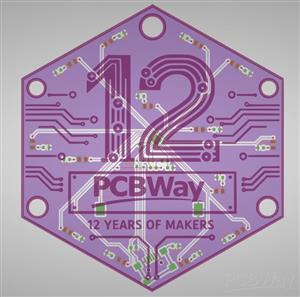
PCBWay 12 Years of Makers Anniversary Badge
The PCBWay 12 Years of Makers Anniversary Badge is a commemorative electronic badge designed to celebrate twelve years of innovation, engineering, and maker culture. The badge combines custom PCB artwork, embedded electronics, and programmable LED animations in a compact, battery-powered design.
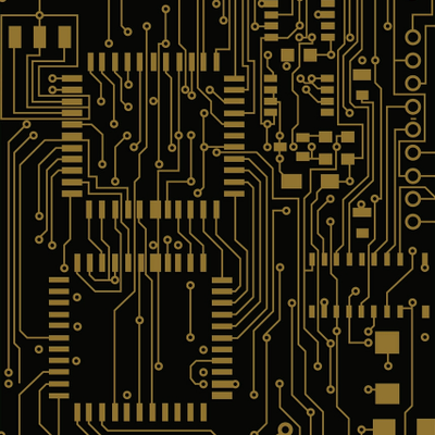
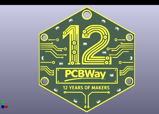
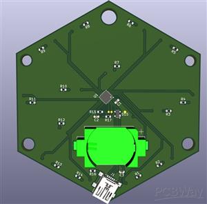
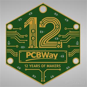
The board itself serves both as an electronic circuit and as a decorative object. The front side features a large stylized "12" graphic integrated into the PCB artwork, surrounded by traces that resemble electronic circuitry, emphasizing the engineering and manufacturing heritage of PCBWay.
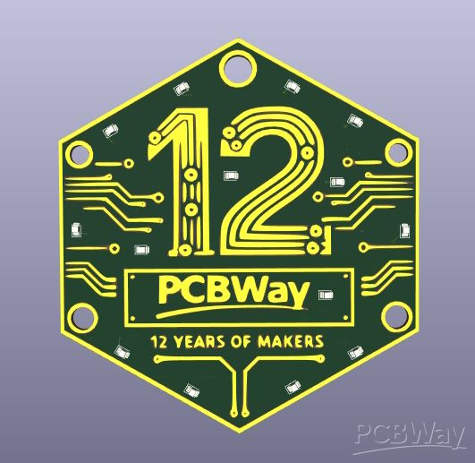
Key mechanical features include:
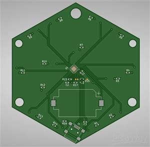
- Hexagonal shield-inspired PCB outline
- Five mounting holes for lanyards, clips, or accessories
- High-contrast PCB artwork with gold-colored traces
- Large central anniversary logo
- Compact wearable form factor
The PCB artwork was designed to integrate decorative copper traces directly into the visual identity of the badge.
The badge is based on a low-power ARM Cortex-M0+ microcontroller and a set of 14 individually controlled LEDs.
Main electronic components:
- ATSAMD11 microcontroller
- 14 surface-mount LEDs
- CR2032 coin-cell battery holder
- Integrated USB programming interface
The design focuses on low power consumption while providing sufficient processing capability for advanced LED animations.
Microcontroller
The badge uses the ATSAMD11 microcontroller from Microchip.
Key features:
- ARM Cortex-M0+ CPU
- 32-bit architecture
- Low power consumption
- USB device support
- Flash memory for animation storage
- Multiple GPIO pins for LED control
The microcontroller executes animation sequences stored in flash memory and controls all LED timing and effects.
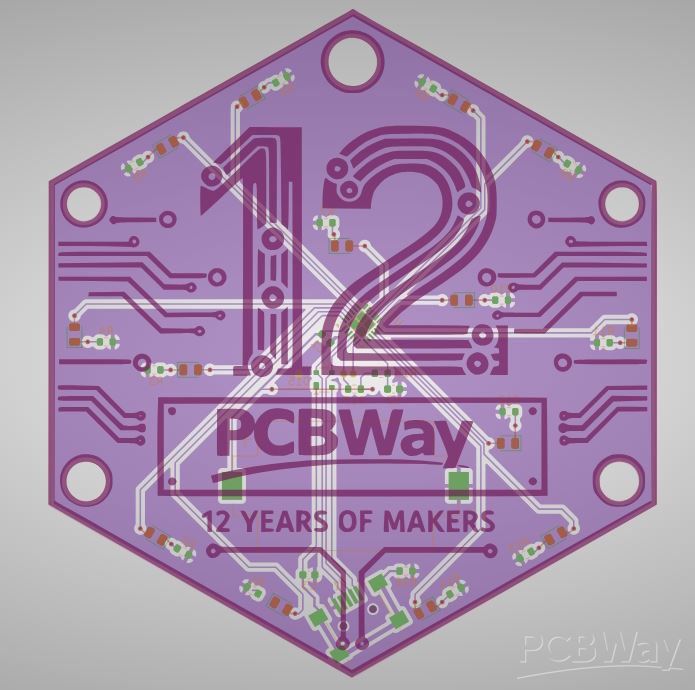
LED System
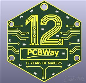
The badge contains 14 surface-mount LEDs positioned around the PCB.
The LED arrangement was selected to:
- Highlight the shape of the badge
- Emphasize the "12" anniversary artwork
- Provide visually balanced animation effects
- Enable directional and rotational lighting patterns
Each LED can be controlled independently, allowing the creation of:
- Static patterns
- Blink effects
- Chase effects
- Rotating animations
- Fade effects
- Breathing effects
- Random sparkle effects
The distribution of LEDs across the badge allows complex visual animations despite the relatively small number of light sources.
Power System
The badge is powered by a standard CR2032 lithium coin cell.
Characteristics:
- Nominal voltage: 3 V
- Typical capacity: approximately 220 mAh
- User-replaceable battery
- Worldwide availability
- Low cost
Power-saving techniques include:
- Microcontroller sleep modes
- Optimized LED duty cycles
- Adjustable brightness control
- Efficient animation scheduling
Depending on the selected animation, operating time can range from several days to multiple weeks.
USB Interface
A USB connector is integrated directly into the badge.
The USB interface provides:
- Firmware updates
- Animation uploads
- Configuration access
- Development and debugging support
The badge appears as a USB device when connected to a computer, allowing direct communication with the Badge Sequencer software.
Firmware Architecture
The firmware is designed around a sequence-based animation engine.
Each animation is represented as a sequence of programmable steps.
A step contains:
- LED state mask
- Duration
- Brightness level
- Effect parameters
The firmware continuously loops through the programmed sequence and updates the LEDs according to the timing information stored in memory.
This architecture allows complex animations while keeping memory requirements low.
The visual identity of the badge combines traditional PCB aesthetics with anniversary-themed graphics.
The combination of electronics and custom artwork makes the badge both a functional development platform and a collectible commemorative item.
The PCBWay 12 Years of Makers Anniversary Badge is a compact, programmable electronic badge that celebrates twelve years of innovation in PCB manufacturing and the global maker community. By combining custom PCB artwork, low-power embedded electronics, USB programmability, and dynamic LED animations, the badge serves as both a collectible commemorative item and a versatile interactive electronics platform.
Technical Specifications
Microcontroller: ATSAMD11 (ARM Cortex-M0+)
LED Count: 14
Power Supply: CR2032 coin-cell battery
Programming Interface: USB
Animation Storage: Internal Flash Memory
Operating Voltage: 3 V
Platform Support: Programmable from Windows and Linux using Badge Sequencer software
Badge Sequencer – LED Badge Programming Studio

Badge Sequencer is a cross-platform desktop application developed in C++ and Qt 6 for creating, simulating, and programming animation sequences for a custom electronic event badge based on the ATSAMD11 microcontroller.
The software provides an intuitive graphical environment for designing LED animations, previewing them in real time, estimating battery life, and uploading the finished program directly to the badge.
The application is designed for makers, electronics enthusiasts, conference organizers, and badge creators who need a simple yet powerful tool for developing custom LED effects without writing embedded code.
Main Features
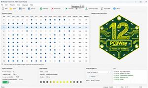
1. Sequence Editor
The left side of the application contains a sequence editor represented as a table.
Each row corresponds to a single animation step and contains:
- LED1–LED14 states
- Duration in milliseconds
- Effect type
- Brightness level
Users can:
- Add steps
- Remove steps
- Duplicate steps
- Reorder steps
- Edit durations
- Configure individual LED states
The sequence editor allows precise control over the badge animation timeline.
2. Interactive Badge View
The right side of the application displays a high-resolution image of the actual badge.
All 14 LED positions are mapped directly onto the badge image.
Users can click LEDs directly on the badge preview to:
- Turn LEDs on or off
- Edit the currently selected sequence step
- Visualize animation states instantly
This graphical editing approach eliminates the need to manually toggle checkboxes in the sequence table.
3. Real-Time Simulation
The simulator reproduces the behavior of the physical badge.
Supported simulation features include:
- Static LED states
- Blink effects
- Fade-in and fade-out transitions
- PWM brightness control
- Continuous looping
- Step-by-step preview
The simulator updates the badge image in real time and provides an accurate representation of how the animation will appear on the physical hardware.
4. Animation Effects
Static - LED remains continuously ON during the step.
Blink - LED alternates between ON and OFF states. Configurable parameters: Duration and Frequency
Fade - Smooth transition between OFF and ON states. Supports: Fade-in , Fade-out , Fade-in/out cycle ,
PWM Brightness - Allows precise brightness control. Brightness range: 0–255. This effect enables smooth lighting variations while minimizing power consumption.
5. Battery Runtime Estimation
The software includes a power consumption analyzer.
Using number of active LEDs, brightness settings, animation timing, ATSAMD11 current consumption the application calculates average current draw, estimated CR2032 battery runtime and power usage statistics.
This feature helps optimize animations for maximum battery life.
6. USB Programming
Badge Sequencer can program the badge directly through USB.
Supported methods:
- USB CDC Serial
- Future UF2 Bootloader support
Programming workflow:
1. Connect the badge via USB.
2. Click "Upload to Badge".
3. The application detects the ATSAMD11 device.
4. The sequence is converted into binary format.
5. The program is transferred to flash memory.
6. The badge automatically restarts.
No external programming tools are required.
Badge Sequencer provides a complete development environment for creating, simulating, and programming LED animations on ATSAMD11-based event badges. By combining an intuitive graphical editor, real-time simulation, power analysis, and direct USB programming, it enables users to create professional-quality animations without requiring embedded firmware development experience.
PCBWay 12 Years of Makers Anniversary Badge
*PCBWay community is a sharing platform. We are not responsible for any design issues and parameter issues (board thickness, surface finish, etc.) you choose.


Raspberry Pi 5 7 Inch Touch Screen IPS 1024x600 HD LCD HDMI-compatible Display for RPI 4B 3B+ OPI 5 AIDA64 PC Secondary Screen(Without Speaker)
BUY NOW


- Comments(0)
- Likes(0)
More by Miroslaw Szymczyk
-
-
-
-
-
ARPS-2 – Arduino-Compatible Robot Project Shield for Arduino UNO
2685 0 5 -
A Compact Charging Breakout Board For Waveshare ESP32-C3
3166 3 8 -
AI-driven LoRa & LLM-enabled Kiosk & Food Delivery System
3429 2 2 -
-


