


|
Microchip studio |
|

|
KiCADKicad
|
|
|
|
FreeCADFree Software Foundation, Inc.
|
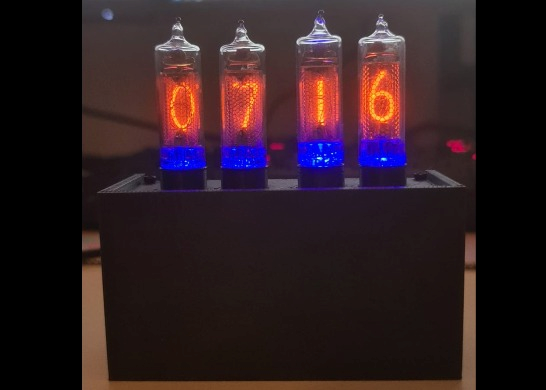
Nixie Tube Clock
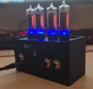
This project is an IN-16 Nixie tube clock powered by USB-C. It combines a high-voltage tube display with embedded electronics, GNSS time synchronization, a real-time clock, USB 2.0 serial communication, current monitoring, temperature sensing and LED backlighting.
Features
- Display: 4x IN-16 Nixie tubes
- Backlight: Blue LED background lighting under each tube
- Power input: USB-C powered
- USB interface: USB 2.0 device interface with serial COM port output
- Microcontroller: ATSAMD21J18A
- Time synchronization: u-blox NEO-M8N GNSS module
- RTC backup: RV-3028-C7 real-time clock with supercapacitor backup
- RTC holdover: Tested for about two weeks without USB power
- High-voltage supply: Approximately 180 V for the Nixie tubes
- Current monitoring: Nixie tube supply current measurement
- Sensors: Temperature sensors connected over I2C
- User input: External buttons for mode selection and manual time/date setting
- Display modes: Time-only mode and automatic time/date/year cycle mode
- Serial menu: USB COM port menu for configuration, testing and debugging
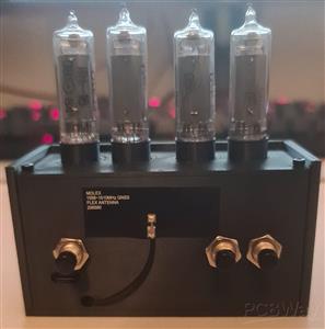
- Enclosure: Custom 3D printed housing with antenna, button and programming cutouts
Why I built it
The idea for this project started because I wanted to build something around timekeeping and the ATSAMD21 microcontroller. I received a u-blox NEO-M8N GNSS module from work, and that gave me the idea to build a clock with GNSS time synchronization. Since the ATSAMD21 is a microcontroller that we use very often at work, this project was a good opportunity for me to learn more about the software side of a device that I already knew well from the hardware side.
I had wanted to build a Nixie tube clock for a long time. When I was younger, I did not have enough time, experience or electronics knowledge to design and build one properly. Now, after gaining much more experience as a hardware designer, I wanted to finally build my own version.
I also had not soldered a bigger private project for a while, so I intentionally used mostly 1206 components. This makes the board easier to solder by hand and easier to debug. The RTC is one of the few smaller and more difficult parts.
How it works
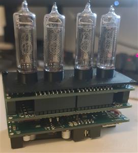
The clock uses four IN-16 Nixie tubes to display the time. Each tube has a blue LED below it for background lighting. The main controller is an ATSAMD21J18A.
Time can be synchronized using the u-blox NEO-M8N GNSS module, while an RV-3028-C7 real-time clock keeps the time when GNSS is not available. The RTC is backed up by a supercapacitor, so the clock can keep the time even when USB power is disconnected. In my tests, the RTC backup worked for about two weeks.
The device is powered through USB-C. From the 5 V input, the board generates 3.3 V for the microcontroller and logic, 9 V for the high-voltage stage, and 180 V for the Nixie tubes.
The Nixie cathodes are switched by high-voltage transistor arrays, controlled through CD74HC4067 multiplexers. This reduces the number of microcontroller pins needed to drive the four tubes. The design also includes temperature sensors, user buttons and current measurement for the Nixie supply.
To protect the Nixie tubes from cathode poisoning, the firmware periodically activates all digits. Every 5 minutes, all cathodes are briefly driven for about 2 seconds. This helps to keep rarely used digits active and reduces uneven cathode wear.
User interface and clock functions
The clock has both a physical button interface and a USB serial interface. This makes it usable as a standalone clock, but also easy to configure and debug from a computer.
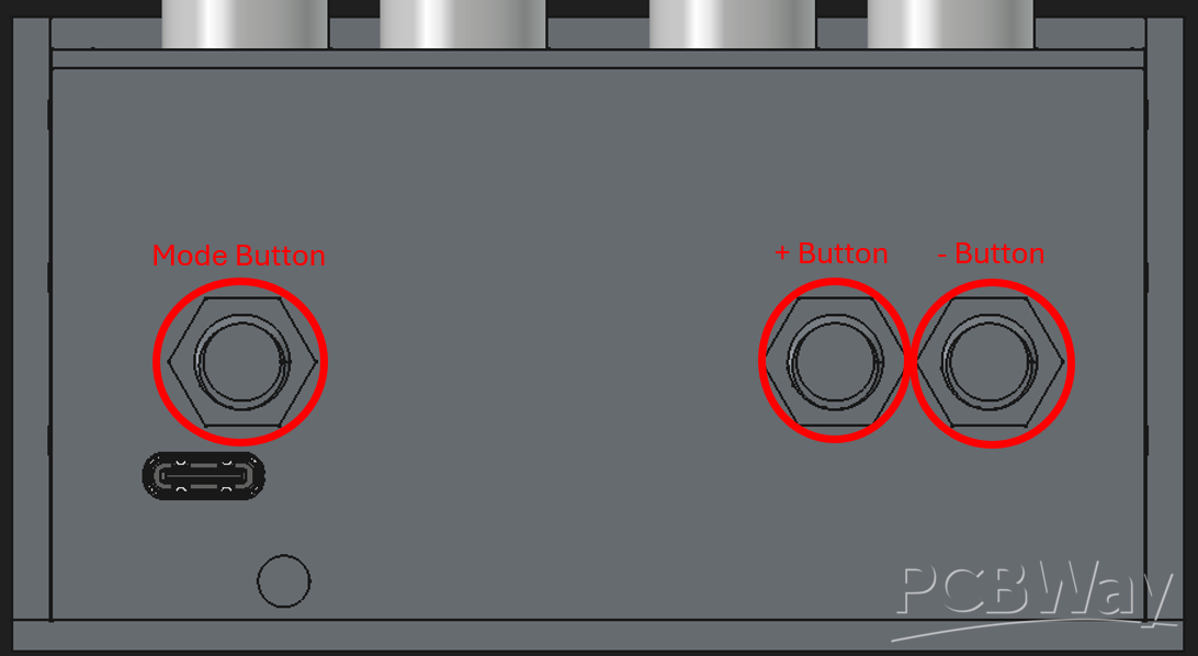
The physical user interface is based on external buttons. A short press on the Mode button switches between the main display modes.
Mode 1 is the normal clock mode. In this mode, the Nixie tubes only show the current time.
Mode 2 is an information mode. In this mode, the display cycles every 20 seconds between the current time, the date in DD.MM format, and the year in YYYY format. This allows the clock to show more information while still keeping the display simple.
A long press on the Mode button opens the time and date settings menu. In this menu, the user can manually set the time and date. This is useful if no GNSS signal is available, or if the user wants to adjust the time manually. The additional buttons are used to increase or decrease the selected value. To step through the settings the mode button is used.
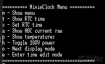
In addition to the buttons, the clock also provides a USB 2.0 device interface. When connected to a computer, the clock appears as a serial COM port. Through this interface, the clock can output status and debug information. It also provides a serial menu that can be used for configuration, testing and development.
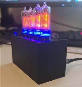
Mechanical design
The enclosure was designed in FreeCAD and is made from 3D printed parts. The housing includes holes for the buttons and antenna, as well as a cutout for the SWD programming/debug connector. This allows the firmware to be programmed or debugged without fully disassembling the clock.
Assembly notes
Detailed assembly instructions are included as a separate PDF in the “Other files for Assembly” section. The PDF covers the Nixie tube assembly, PCB stack, button wiring, antenna connection, 3D printed housing and final installation.
The included iBOM files are intended as visual placement references, but the final BOM should always be checked because the iBOM may show parts marked as “Do Not Place”.
Project goal
For me, this project was not only about building a Nixie clock. I wanted to combine several things I wanted to learn and test in one complete device.
The main goal was to get deeper into the software side of the ATSAMD21. I already knew the microcontroller well from a hardware point of view, but I wanted to improve my firmware skills with a real project.
Another goal was to design my own high-voltage step-up supply for the Nixie tubes, instead of only copying a basic reference circuit from a datasheet. I wanted to understand the circuit better and adapt it to the requirements of this clock.
Current firmware status
Because of limited time due to work and university, the firmware is still being improved. The basic clock functions, display modes, manual time/date setting and serial output are implemented, but the u-blox NEO-M8N GNSS integration is not fully finished yet.
The hardware for GNSS time synchronization is already included, and the goal is to use the GNSS module to automatically synchronize the RTC and system time in the future.
Nixie Tube Clock
Project images are for reference only. Actual production is based on the manufacturing files on the project page.
Please review the designer's notes (e.g., PCB thickness) and select the appropriate options.
PCBWay is not responsible
for issues caused by unsuitable parameter selections.
For more important ordering information, please refer to
Read More


Raspberry Pi 5 7 Inch Touch Screen IPS 1024x600 HD LCD HDMI-compatible Display for RPI 4B 3B+ OPI 5 AIDA64 PC Secondary Screen(Without Speaker)
BUY NOW


- Comments(0)
- Likes(0)
More by Riccardo Kahl
-
Programmable Mist Maker - XIAO / QT PY Extension
1038 2 1 -
RadioHAT - Raspberry Pi radio development platform
841 0 2 -
-
-
-
-
ARPS-2 – Arduino-Compatible Robot Project Shield for Arduino UNO
3296 0 6 -
A Compact Charging Breakout Board For Waveshare ESP32-C3
3914 3 8 -
AI-driven LoRa & LLM-enabled Kiosk & Food Delivery System
4293 2 2


