


|
|
KiCad 10.0 |
|
|
Fusion 360Autodesk
|
Micro Entertainment System
3 months ago, I had never designed a circuit or PCB. But as an avid retro gaming fan, I got to wondering, could a simple MCU emulate the original Nintendo and also output valid NTSC to play on old CRT monitors without the use of an NTSC IC? And here's the catch, could I do all this with vibe coding and having the modern AI toolsets teach me everything I need to design the circuit and PCB?
The answer, much to my surprise, was a resounding YES!
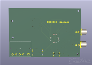
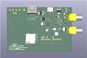
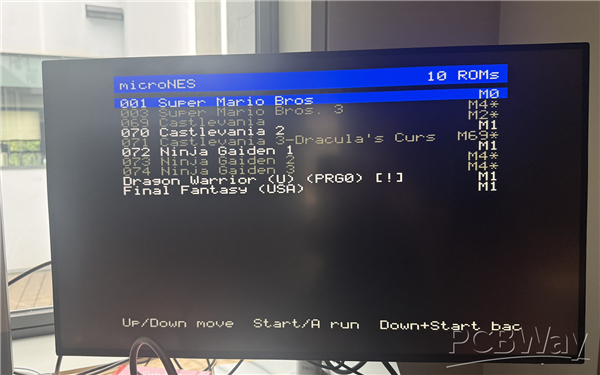
The Micro Entertainment System is an RP2350-based board that outputs both HDMI and composite audio and video. The firmware emulates the original Nintendo Entertainment System and currently supports most games, which can be loaded into the flash on the board via SD card. (Games aren't played directly from SD card for performance reasons).
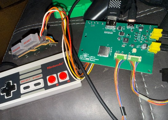
For extra credit, I decided to make the board use the original NES power and reset switch (using KiCad to make the custom footprint for that part, of course). And once I was harvesting original NES parts, I decided to use the original controller port headers from the NES console, so original NES controllers can plug directly into the Micro Entertainment System for minimal latency gameplay! I have tuned the firmware to get within tenths of a percent of original console frame rate, and in my experience playing on this device, it feels incredibly close to playing on the original console with respect to timing very difficult input tricks (that require frame perfect inputs). Of course, if you don't want to harvest parts, you can simply install your own switch on those two pads of the board, ignore the LED and reset switch pads, and get two inexpensive knockoff controllers, cut off the connectors, and hand wire the clock, latch, data, power, and gnd wires to those five pins on each of the controller ports. I have verified that non-Nintendo controllers work with this board even though we only supply 3.3v instead of what the original NES supplies (5v) to the controllers.
The video DAC is implemented with a simple resistor ladder. I did that as a standalone PCB in late March and used a Pi Pico 2 to prove the concept. Then in early May, I got to work developing the full system on a single board (including adding HDMI and SD card after some breadboard testing). The current rev of the board was fully designed in May, 2026. Here's the video I made the first night the previous rev of the board got up and running (I had a bug where I switched a couple pads). The current rev is a bit larger to fit nicely in the case I'm working on as well (future work!).
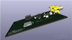
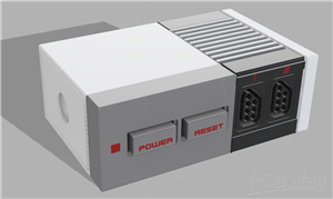
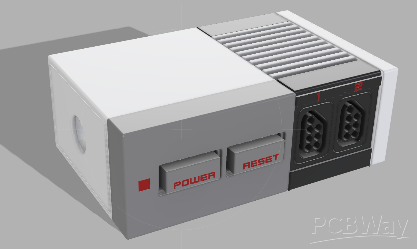
And here's a render of what I'd like the case to be like (thank you Jerry for this render!):
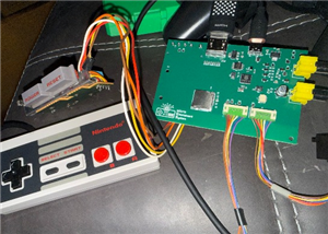
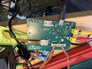
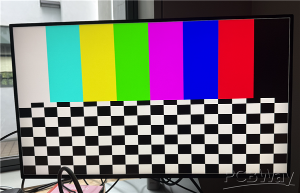
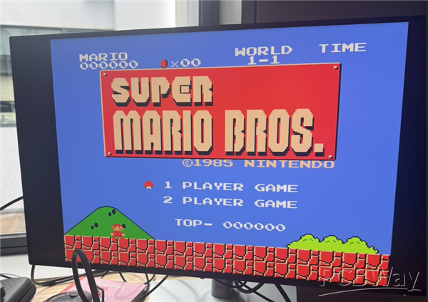
And some other photos of the device in operation.
Original breadboard proof of concept with resistor ladder and pi pico 2:
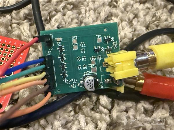
First audio and video DAC (connected to Pi Pico 2):
HDMI bringup pictures (via HSTX pins on RP2350):
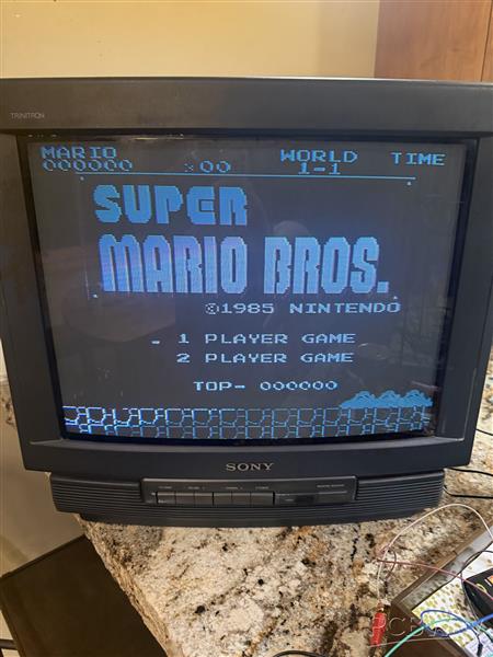
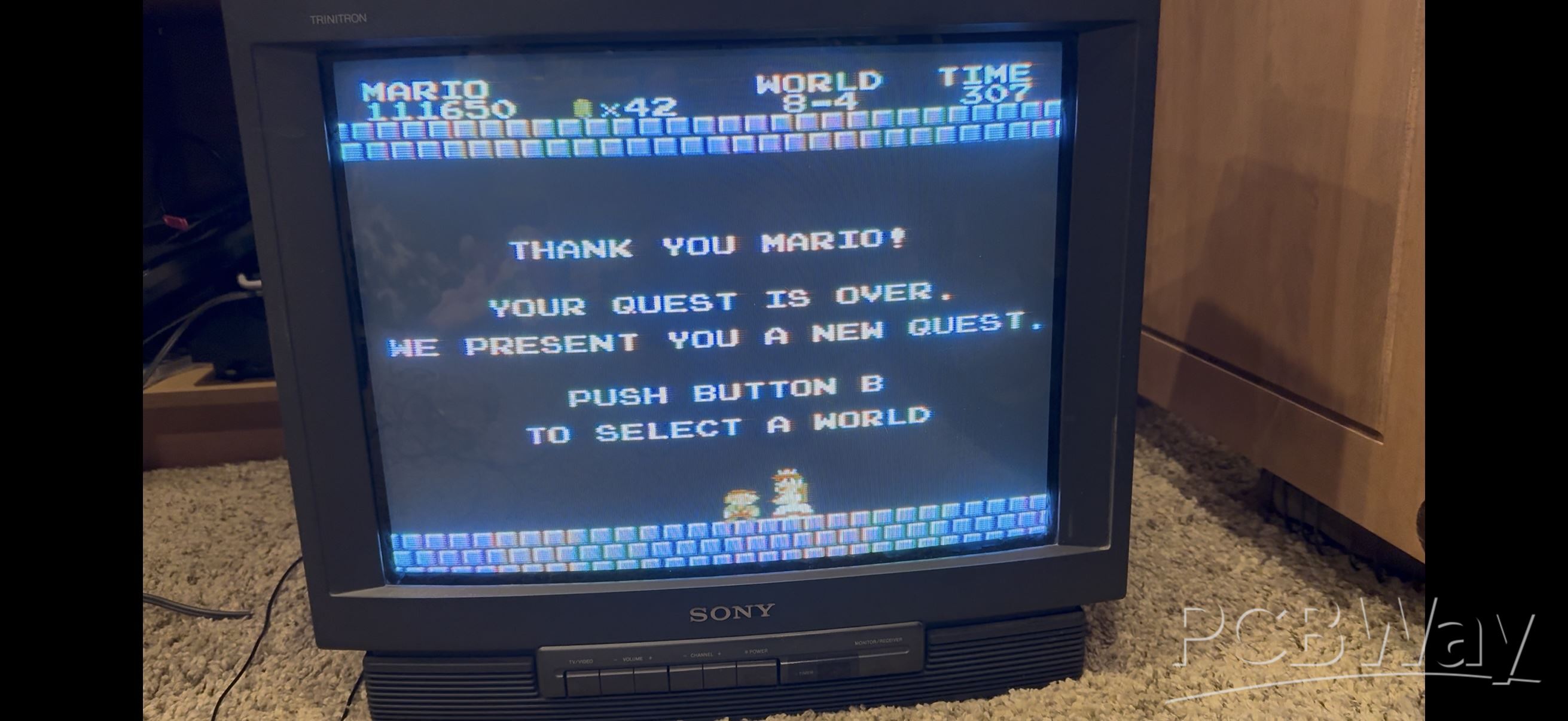
And to conclude, here's a picture of the very first time I beat Super Mario Bros. on this custom built device!
Thanks for taking a look at this!
Micro Entertainment System
Project images are for reference only. Actual production is based on the manufacturing files on the project page.
Please review the designer's notes (e.g., PCB thickness) and select the appropriate options.
PCBWay is not responsible
for issues caused by unsuitable parameter selections.
For more important ordering information, please refer to
Read More


Raspberry Pi 5 7 Inch Touch Screen IPS 1024x600 HD LCD HDMI-compatible Display for RPI 4B 3B+ OPI 5 AIDA64 PC Secondary Screen(Without Speaker)
BUY NOW


- Comments(0)
- Likes(1)
- 1 USER VOTES
- YOUR VOTE 0.00 0.00

-
10design
-
10usability
-
10creativity
-
10content
 More by Ben Chelf
-
Programmable Mist Maker - XIAO / QT PY Extension
1076 2 1 -
RadioHAT - Raspberry Pi radio development platform
891 0 2 -
-
-
-
-
ARPS-2 – Arduino-Compatible Robot Project Shield for Arduino UNO
3334 0 6 -
A Compact Charging Breakout Board For Waveshare ESP32-C3
3946 3 8 -
AI-driven LoRa & LLM-enabled Kiosk & Food Delivery System
4336 2 2


