


|
KiCad 9.0 |
|

|
arduino IDEArduino
|
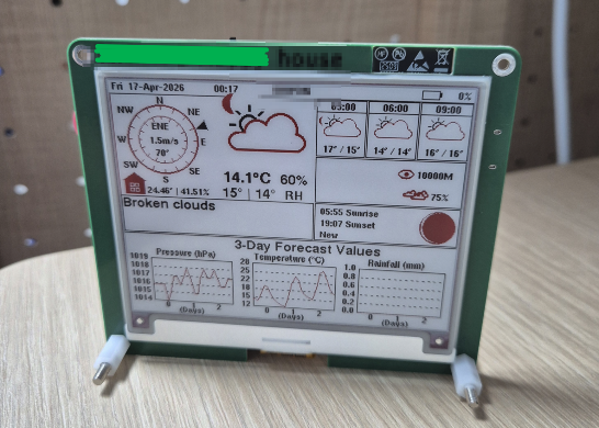
Desktop weather station using E-ink display and ESP32-S3-WROOM
this is a PCBWay-sponsored project.
I refer to this project from Circuit digest "How to Build a Desktop Weather Station Using ESP32 and E-ink Display".
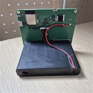
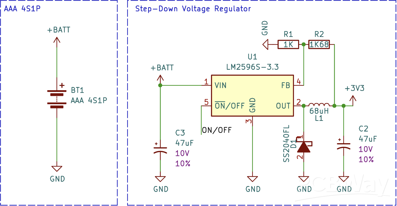
The original project used a charging internal battery as a power source but I thought AA cell batteries would be easy to use because AA batteries can be bought on the shelf of counter.
I changed LDO circuit to DCDC convertor for the better battery life. The converter used is the LM2596S.
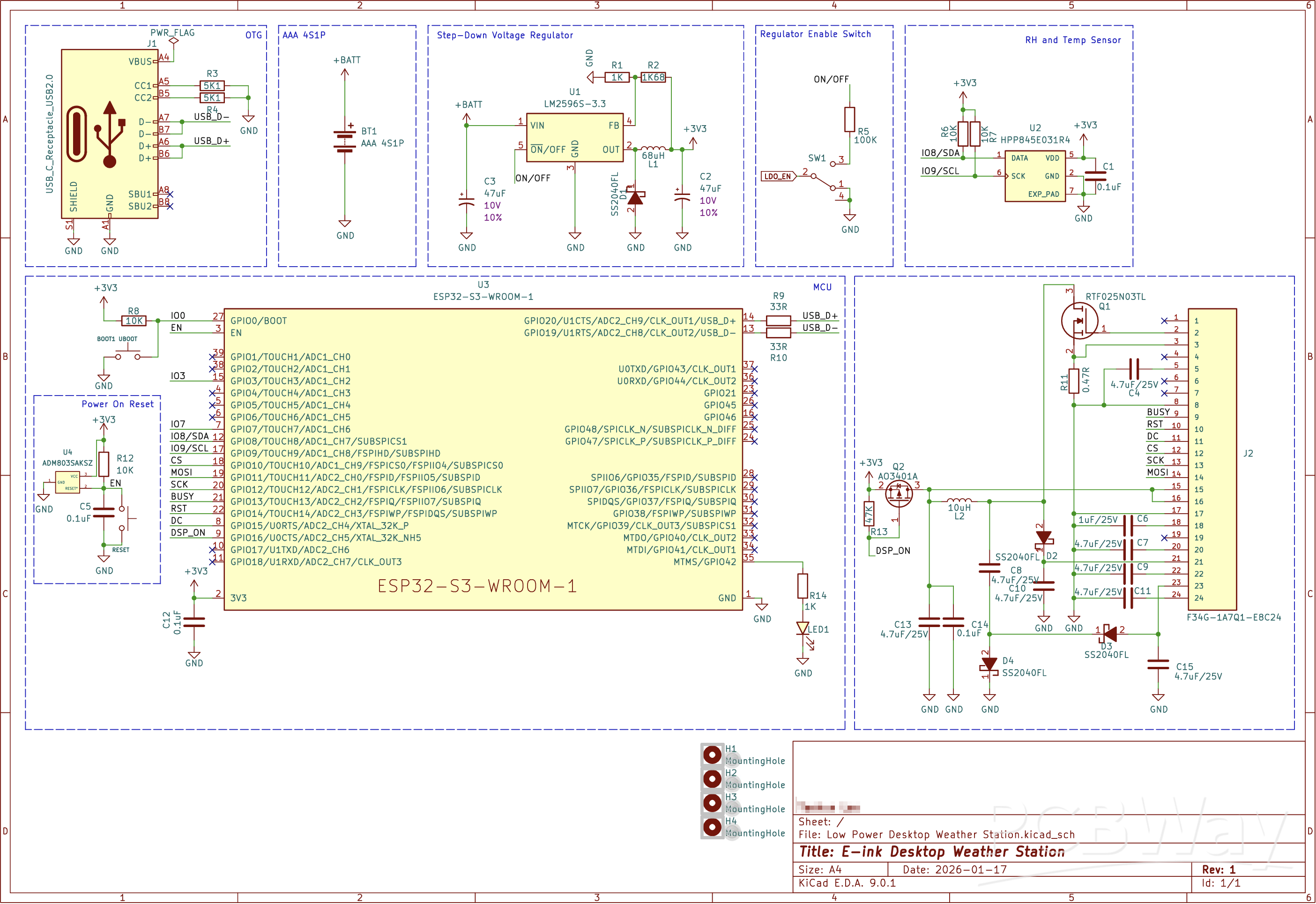
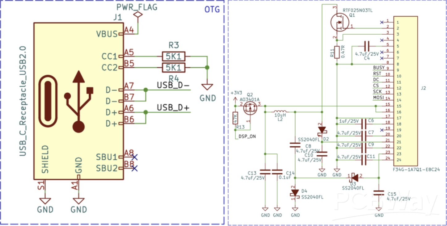
This is the input/output port section. The input is a USB-C type port. The main controller, ESP32-S3, has a built-in USB 2.0 Full-Speed (12 Mbps) PHY, which allows it to directly receive and transmit USB signals without the need for a separate USB-UART bridge chip. It is used for flashing code onto the ESP32-S3.
There was a mistake in the USB input circuit, but I will cover that in a future post.
For the output, there is an FFC cable connector that sends signals to the E-paper display. Through SPI signals, it delivers the display output data to the E-paper module.
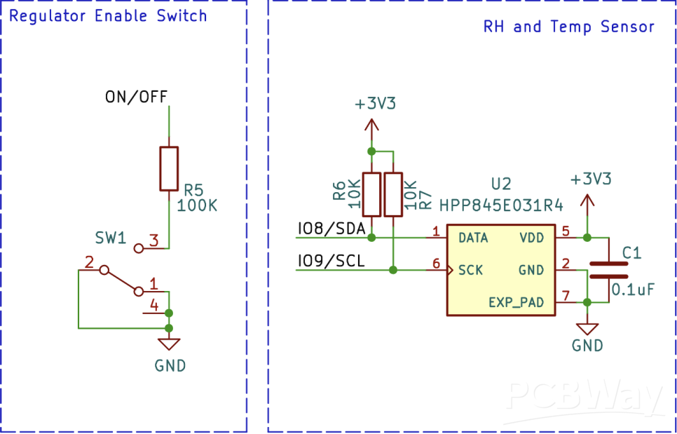
The step-down regulator LM2596S is controlled by a switch and a temperature-humidity sensor. Since the LM2596S turns ON when the ON/OFF pin is Low and OFF when the pin is High, I connected this pin to a switch to configure a circuit that can turn the LM2596S on and off.
For the temperature-humidity sensor, I used the HPP845E031R4, manufactured by TE Connectivity. It is a digital humidity and temperature sensor that communicates via the I2C interface, detecting the temperature and humidity of the room where the weather station is located and sending the data to the microcontroller.
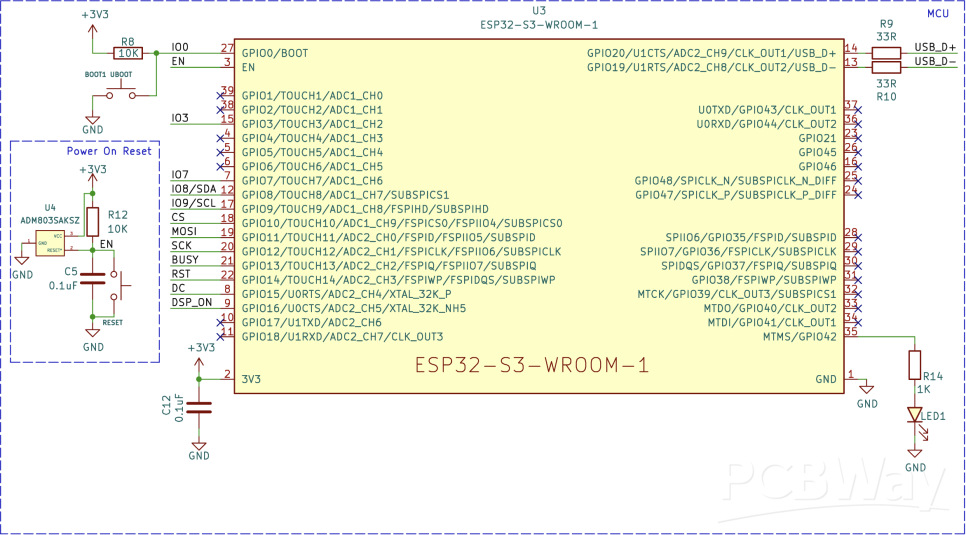
The main controller is the ESP32-S3-WROOM-1, a microprocessor developed by Espressif Systems. It comes with a built-in Wi-Fi + Bluetooth LE module, and I plan to use Wi-Fi to receive weather information.
It provides 45 GPIO pins and supports various interfaces such as SPI, I2C, I2S, UART, PWM, ADC, and DAC. Ultimately, all data and signals flow into and out of this microcontroller.
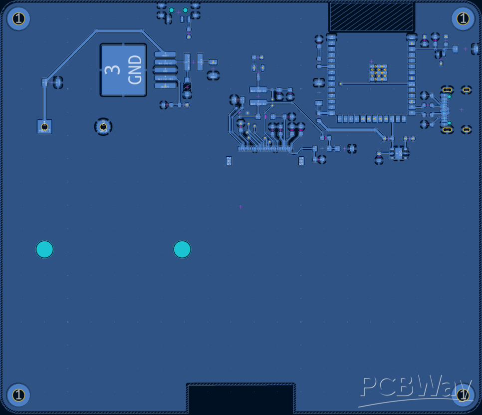
Let’s take a look at the PCB. The PCB was designed as a 2-layer board, which was sufficient since the design is not very complex. As the display will be attached to the front side, all the components were placed on the back side. The front layer is set as the 3.3V power plane, while the back layer is configured as the GND plane.

All the components are placed on the back side. The ESP32-S3-WROOM-1 microcontrollerhas an antenna for Wi-Fi and Bluetooth wireless communication, and to ensure smooth wireless performance, I created a PCB cutout at the antenna area.
The code is originated from open source ESP32-e-Paper-Weather-Display.
https://github.com/G6EJD/ESP32-e-Paper-Weather-Display.git
In the config.h header file, you need to enter your Wi-Fi ID in the ssidfield and your password in the passwordfield. For the apikey, you should insert your OpenWeatherMap API keyto receive weather information. The LAT and LON fields must be filled with the latitude and longitude of the location from which you want to obtain the weather data.
Desktop weather station using E-ink display and ESP32-S3-WROOM


Raspberry Pi 5 7 Inch Touch Screen IPS 1024x600 HD LCD HDMI-compatible Display for RPI 4B 3B+ OPI 5 AIDA64 PC Secondary Screen(Without Speaker)
BUY NOW


- Comments(2)
- Likes(2)
 More by Engineer
-
Programmable Mist Maker - XIAO / QT PY Extension
168 0 0 -
RadioHAT - Raspberry Pi radio development platform
176 0 1 -
-
-
-
-
ARPS-2 – Arduino-Compatible Robot Project Shield for Arduino UNO
2763 0 5 -
A Compact Charging Breakout Board For Waveshare ESP32-C3
3267 3 8 -
AI-driven LoRa & LLM-enabled Kiosk & Food Delivery System
3520 2 2


