

DIY Soldering Station
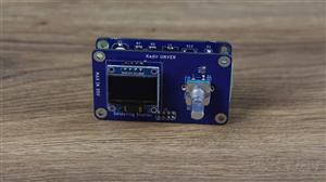
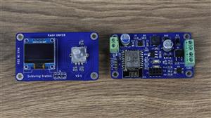
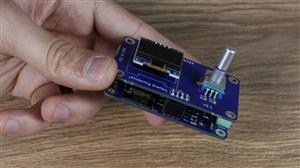
Bu projede ESP 12F kullanarak bir havya istasyonu yaptım. Sıcaklık kontrolü bir mosfet ve mosfet sürücü yapısı ile gerçekleşmektedir.


#include <Wire.h>
#include "SSD1306Wire.h"

SSD1306Wire display(0x3c, SDA, SCL);

#define tempSensor A0
#define iron 12


int sayac = 20; // İleri ve geri sayacak sayacımız
int yon;        // Dönüş yönünü kontrol kaydettiğimiz değişken
int clk_son;    // Dönüş yönünün son bildiğimiz hali
int clk_simdi;  // Dönüş yönünün mevcut algıladığımız hali

int clk = 9;     // CLK pini
int dt = 10;    // DT pini
int buton = 13; // Buton (SW) Pini


int minADC  = 77,        //okunan minumum adc
maxADC  = 871,      //okunan maksimum adc
pwm=0;

int setTemp=0,readingTemp=0;
int average=0;


unsigned long previousMillis = 0;  // Önceki zaman bilgisini saklamak için değişken
const long interval = 50;          // Belirlenen aralık (milisaniye cinsinden)

void setup() {
  Serial.begin(9600);


  previousMillis = millis();
  display.init();
  display.flipScreenVertically();
  display.setFont(ArialMT_Plain_10);
  display.clear();
  display.setTextAlignment(TEXT_ALIGN_CENTER);
  display.setFont(ArialMT_Plain_16);
  display.drawString(60, 10, "Kadir Unver");

  for (int i = 0; i < 128; i++) {
    display.drawLine(0, 32, i, 32);
    display.drawLine(0, 33, i, 33);
    display.drawLine(0, 34, i, 34);
    display.display();
    delay(10);
  }

  display.display();

  pinMode(iron, OUTPUT);

  pinMode(clk, INPUT);
  pinMode(dt, INPUT);
  pinMode(buton, INPUT);

  clk_son = digitalRead(clk);           // CLK pinini ilk kez okuyup değer atıyoruz
 }


void loop() {

  readingTemp=0;
  for (int i = 0; i < 100; i++) { readingTemp += analogRead(tempSensor);  }

  average = readingTemp / 100;
  readingTemp=map(average,minADC,maxADC,25,420);

  rotary();

  unsigned long currentMillis = millis();
  if (currentMillis - previousMillis >= interval) {
    oled();
    previousMillis = currentMillis;
  }

  if(sayac==0){  pwm=0;  }

  else if(readingTemp-8<=sayac){ pwm=255;   }

  else{ pwm=0; }

  analogWrite(iron,pwm);

 }

void oled(){
  display.clear();

  display.setTextAlignment(TEXT_ALIGN_LEFT);
  display.setFont(ArialMT_Plain_16);
  display.drawString(0, 0, "Set Temp:");
  display.setTextAlignment(TEXT_ALIGN_LEFT);
  display.setFont(ArialMT_Plain_16);
  display.drawString(80, 0, String(sayac));

  display.setTextAlignment(TEXT_ALIGN_LEFT);
  display.setFont(ArialMT_Plain_24);
  display.drawString(0, 30, "Temp:");
  display.setFont(ArialMT_Plain_24);
  display.drawString(75, 30, String(readingTemp-8));
  display.display();


}
 void rotary(){
  clk_simdi = digitalRead(clk);         // Mevcut durumu okuyalım
  if (clk_simdi != clk_son) {           // Değişiklik olup olmadığına bakalım
    if (digitalRead(dt) == clk_simdi) { // CLK önce değişmiş, yani saat yönüne dönmüş
      sayac=sayac+10;                   // Sayacı 1 artıralım
      yon = true;                       // Yönü de kaydedelim
      if(sayac>420){
        sayac=20;
      }
    }
    else {                              // DT önce değişmiş, yani saat yönünün tersi
      sayac=sayac-10;
      if(sayac<20){ sayac=20; }
      yon = false;                      // dönme yünü kayıtedildi
    }


  }

  clk_son = clk_simdi;                   // Sonraki algılama öncesinde değerleri eşitleyelim

  if (digitalRead(buton) == LOW && sayac != 0) {  // Butona basılmış ve sayacı sıfırlıyoruz
    sayac = 20;
    Serial.println("Sayaç Sıfırlandı");
  }
 }
DIY Soldering Station
Project images are for reference only. Actual production is based on the manufacturing files on the project page.
Please review the designer's notes (e.g., PCB thickness) and select the appropriate options.
PCBWay is not responsible
for issues caused by unsuitable parameter selections.
For more important ordering information, please refer to
Read More









Raspberry Pi 5 7 Inch Touch Screen IPS 1024x600 HD LCD HDMI-compatible Display for RPI 4B 3B+ OPI 5 AIDA64 PC Secondary Screen(Without Speaker)
BUY NOW


- Comments(0)
- Likes(9)

More by Abdulkadir ÜNVER
-
 home assistant
Ev otomasyonlarında ve ya dekor için kullanılabilir.https://youtu.be/BtKPsOtp3JA
home assistant
Ev otomasyonlarında ve ya dekor için kullanılabilir.https://youtu.be/BtKPsOtp3JA
-
 2+1 amplifier circuit TDA2040
Important NOTEOnly r19,c1,r20 r24,c31,r25 will be soldered in the low pass filter section in the cir...
2+1 amplifier circuit TDA2040
Important NOTEOnly r19,c1,r20 r24,c31,r25 will be soldered in the low pass filter section in the cir...
-
 İnduction Heater Design
IMPORTANT NOTEWhen assembling the PCB, the MOSFETs must be mounted with a thermal pad and insulated ...
İnduction Heater Design
IMPORTANT NOTEWhen assembling the PCB, the MOSFETs must be mounted with a thermal pad and insulated ...
-
 DIY Soldering Station
Bu projede ESP 12F kullanarak bir havya istasyonu yaptım. Sıcaklık kontrolü bir mosfet ve mosfet sür...
DIY Soldering Station
Bu projede ESP 12F kullanarak bir havya istasyonu yaptım. Sıcaklık kontrolü bir mosfet ve mosfet sür...
-
 dc_motor_driver
ÖNEMLİ NOTdevre şemasında d1 ve d2 diyotlarının birbirine ters olması gerekmektedir. Devre tasarımın...
dc_motor_driver
ÖNEMLİ NOTdevre şemasında d1 ve d2 diyotlarının birbirine ters olması gerekmektedir. Devre tasarımın...
-
 ESP Weather Station
 and clock.
ESP Weather Station
ESP Weather Station and clock.
-
 Capacitor Led Driver
https://youtu.be/TIRHYlAV5L8Zener diode is not necessary for the led driver circuit. It can be used...
Capacitor Led Driver
https://youtu.be/TIRHYlAV5L8Zener diode is not necessary for the led driver circuit. It can be used...
-
 LM2596S POWE SUPPLY- CURRENT LIMITED
you can watch youtube video for explanation of circuit diagramhttps://youtu.be/koqxd6jSiJE
LM2596S POWE SUPPLY- CURRENT LIMITED
you can watch youtube video for explanation of circuit diagramhttps://youtu.be/koqxd6jSiJE
-
 LED CONTROL BOARD
this project will increase your fun while listening to music
LED CONTROL BOARD
this project will increase your fun while listening to music
-
 Robot Control Board
this project is robot controller board
Robot Control Board
this project is robot controller board
-
 esp 12e Wifi RGBW KONTROL
Note:There is a small problem with the circuit board. The enable pin of the ESP12f should be connect...
esp 12e Wifi RGBW KONTROL
Note:There is a small problem with the circuit board. The enable pin of the ESP12f should be connect...
-
 5630 SMD LED
sa? ve sol taraftaki ledlerin art? hatt? birle?tirilmedi?i i?in d??ardan kablo yard?m? ile tamamlanm...
5630 SMD LED
sa? ve sol taraftaki ledlerin art? hatt? birle?tirilmedi?i i?in d??ardan kablo yard?m? ile tamamlanm...
-
Programmable Mist Maker - XIAO / QT PY Extension
2333 2 2 -
RadioHAT - Raspberry Pi radio development platform
2021 0 4 -
-
-
-
ARPS-2 – Arduino-Compatible Robot Project Shield for Arduino UNO
4180 0 6 -
A Compact Charging Breakout Board For Waveshare ESP32-C3
4943 3 8 -
AI-driven LoRa & LLM-enabled Kiosk & Food Delivery System
5722 2 2 -