


|
KiCADKicad
|
Commodore 64 Power Supply Replacement Switchmode Regulator Board
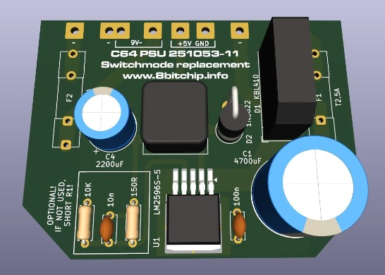
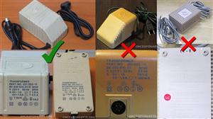
This PCB is a switchmode regulator replacement for Commodore 64 power supplies with part number 251053-11, submarked as BV 830 810.01/II, manufactured by Ismet. This is the so-called "Wedge" model, but with "sharp edges", contrary to the more common "Sloped Wedge" model.
Please note that at least two other types of power supplies bear the 251053-11 model number, the fully potted brick (which usually came with the C64C model) and a "sloped edge" model which is submarked as BV 830 810.01 (without the II). This board is not suited for these power supplies.
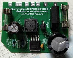
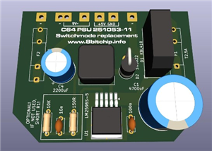
The original board has a linear regulator, which is prone to failure and heats up a lot. This board has a switching regulator, which reduces the heating a lot. The regulator used is LM2596S. It can use either a fixed regulator, LM2596S-5, or the adjustable LM2596S-ADJ.
There is also a provision to boost the output voltage of the fixed regulator to 5.2v, which can help with the cable voltage drop.
My main motivation behind this project was that I had quite a few of these power supplies which either heated up or failed, and I had a stock of LM2596S-5 left over from a previous project. Also, these power supplies are, in my opinion, very repairable. They are just slightly potted and the cover is held with screws.
Building the PCB
The BOM is available in the repository. Note that R1, R2 & C3 are optional. They are used for voltage boosting or setting the output voltage if the adjustable regulator is used. Fuses and fuse holders you can reuse from the original power supply board you will be removing.
Removing the old PCB and heatsink
I ASSUME YOU KNOW WHAT YOU ARE DOING AND THAT YOU ARE DEALING WITH PARTS THAT USE 230V AC!
BE SURE THE POWER SUPPLY IS UNPLUGGED BEFORE PROCEEDING!
Unscrew the bottom of the power supply and remove the lid. Desolder the output cable, noting where which wire is soldered. Also, desolder the wires coming from the transformer to the PCB. Remove the fuses and save them if they are still good.
Prepare a heat-proof container where the power supply can be comfortably placed in, bottom side up. Heat up some water to boiling temperature, and pour it in the container up to the similar level of the resin in the heatsink compartment of the power supply.
After some 30 seconds, use a pair of pliers (and heat-resistant gloves) to pull on the old PCB, and if necessary, the heatsink. You will be able to remove it quite easily and in one piece. Take the power supply from the water and leave it to dry.
After removing the old PCB, you can desolder the fuse holders from it. Other parts, such as diodes and capacitors, and especially the voltage regulator, are not worth salvaging after many years of cooking.
Installing the new PCB
After you have dried the power supply, slot in the new PCB and solder the transformer wires back as they were on the original board. Plug in the power supply, and measure the 5V DC and 9V AC. If these checks pass, continue with soldering the output cable back.
Test and confirm the output on the connector before plugging it to your C64. If necessary, fix the new PCB with some hot glue to prevent movement.
License
This project is Open Hardware licensed under the CERN OHL P v2, released by Marko Šolajić in 2025. You may redistribute and modify this documentation under the terms of the CERN OHL P v2. A copy of the full license is included in file license.txt
Commodore 64 Power Supply Replacement Switchmode Regulator Board
*PCBWay community is a sharing platform. We are not responsible for any design issues and parameter issues (board thickness, surface finish, etc.) you choose.


Raspberry Pi 5 7 Inch Touch Screen IPS 1024x600 HD LCD HDMI-compatible Display for RPI 4B 3B+ OPI 5 AIDA64 PC Secondary Screen(Without Speaker)
BUY NOW


- Comments(0)
- Likes(4)
More by Marko Solajic
-
 Commodore 64 Power Supply Replacement Switchmode Regulator Board
This PCB is a switchmode regulator replacement for Commodore 64 power supplies with part number 2510...
Commodore 64 Power Supply Replacement Switchmode Regulator Board
This PCB is a switchmode regulator replacement for Commodore 64 power supplies with part number 2510...
-
 ZX Spectrum Parallel Interface
The interface adds three 8-bit general-purpose buffered input-output ports to the ZX Spectrum, enabl...
ZX Spectrum Parallel Interface
The interface adds three 8-bit general-purpose buffered input-output ports to the ZX Spectrum, enabl...
-
 Commodore 264 Series Magic Cartridge
Hardware design of a cartridge for the Commodore 264 series of computers - Commodore 16, 116 and plu...
Commodore 264 Series Magic Cartridge
Hardware design of a cartridge for the Commodore 264 series of computers - Commodore 16, 116 and plu...
-
 Universal C64 1MB cartridge
Files are updated to revision 4, improvements:Added footprints for 2 LEDs and 2 resistors, if you ha...
Universal C64 1MB cartridge
Files are updated to revision 4, improvements:Added footprints for 2 LEDs and 2 resistors, if you ha...
-
 C64 Magic Desk 512k Cartridge
DESCRIPTIONThis is the hardware part that accompanies the project of Magic Desk Cartridge Generator ...
C64 Magic Desk 512k Cartridge
DESCRIPTIONThis is the hardware part that accompanies the project of Magic Desk Cartridge Generator ...
-
Programmable Mist Maker - XIAO / QT PY Extension
172 0 0 -
RadioHAT - Raspberry Pi radio development platform
180 0 1 -
-
-
-
-
ARPS-2 – Arduino-Compatible Robot Project Shield for Arduino UNO
2767 0 5 -
A Compact Charging Breakout Board For Waveshare ESP32-C3
3275 3 8 -
AI-driven LoRa & LLM-enabled Kiosk & Food Delivery System
3528 2 2


