


|
KiCADKicad
|
Cable Gradiator
# THE EPIC CABLE GRADIATOR
### A USB Cable Grading Instrument and Data Flow Monitor
*License: CC-BY-NC-SA* · Native KiCad 10 · 4-Layer SMT · Designed by EPIC WIN Pro Media for the *2026 KiCad PCB Design Contest*
GitHub: https://github.com/epicwinpromedia/cable-gradiator
## 1. Executive Summary & Statement of Intent
The **EPIC Cable Gradiator** (Design Code: ECG-2026-V2, “Cable Gradiator”, “GRADI8R”) is a professional-grade desktop instrumentation tool that simultaneously acts as ridiculously indulgent desk jewelry *and* an interactive, hardware-level "data mirror" designed to diagnose, grade, and audit USB cable infrastructure.
The Gradiator completely replaces legacy, slow-to-read multimeters and fragile consumer dongles with an intuitive, solid-state multi-material canvas that visualizes raw energy and data flow as dynamic kinetic light gradients.
“WTF?,” I hear you thinking - “what has this idiot madman done - and for man’s sake, why?!”
I promise: not only is this a:) not as esoteric as it may sound and b:) pretty freaking neat looking - aesthetically - but *actually* something you might use WAY more often than you might think.
### The Core Diagnostic Problem
Every workshop has a "Mystery Cable Drawer" filled with a FAT wad of cords, cables, chargers, adapters and other accessories, and there is ALWAYS the pervasive problem where there are some cables that look premium but are slow, some power-only charging cables, or then there are other completely nondescript black cords that are full-spec, hi-speed carriers for both data and power; you have three different types of connectors and cables could have any of them on either end; you got usb2 and usb3 protocols… and that's assuming the cable works as intended! Any one of the little wires in the cable can wear out over time and prevent the cable from performing reliably.
The Gradiator provides an instant, manual-free answer: drop a mystery cable across its flanks and read its anatomy as *raw light*.
### Practical Impact & Sustainability Focus (Contest Criterion)
Beyond its utility on an engineering bench, the Cable Gradiator addresses a major real-world issue: **electronic waste and diagnostics optimization**. Millions of functional cables are discarded annually simply because users cannot determine their internal conductor capabilities or verify internal hairline fractures. By turning cable grading into an instant visual language, this tool extends the lifecycle of existing cable infrastructure, prevents diagnostic confusion in complex hardware workspaces, and keeps un-optimized consumer cables from disrupting development environments.
## 2. Operational Semantics & Visual Grammar
So, yeah… to get back to that whole “read cable anatomy as “raw light” - don't worry, this isn't a hand-wavy metaphor or sneaky tech-talk - let me explain:
The device features **three operating states plus one error state**, governed by an **automatic mode detection state machine**. This means there is no need to manually switch analysis modes or in/out of charging mode. Mode probing is made intrinsically safe by hardware, not firmware: every scanner drive line passes through a series 10 k$\Omega$ current-limiting resistor, making electrical collisions physically harmless.
In plain language this means that you can simply plug whatever you want into the device and if it fits into the jack it will work with the device.
You cannot break it simply by using it, as opposed to a different other design choices I could have made where, for example, plugging a high-speed USB3 50 watt charging cable into the device would break it, because it didn't have the ability to handle those. There *are* definitely some products like this one out there that are like that - this isn't one of them.
To use this device:
### 2.1 CHARGE Mode
* **Trigger:** Present when live V_{BUS} is detected on **Slot 1 (Primary Left USB-C Input)** with no cross-flank circuit.
* **Visual Grammar:** The full 16×10 matrix acts as a large-format progress bar, filling column-by-column from left to right as the supercapacitor charges. Pixels transition from Red (0–31%) to Yellow (31–62%) to Green (62–100%). Once complete, it enters an ambient "desk jewelry" idle animation.
### 2.2 LOOP Mode (Cable Grading)
* **Trigger:** A single detached cable is connected from any left-flank jack to any right-flank jack with no live external V_{BUS}.
* **Visual Grammar:** The display switches to a **static, low-power physical map** where color encodes the *conductor category*, not current. A continuous horizontal line of gently pulsing pixels means the wire is whole; a dark row means the conductor is broken or missing.
| Matrix Rows | Mapped Protocol Lanes | LOOP Mode Color Space | Meaning |
|---|---|---|---|
| **Rows 1–2** | V_{BUS} & Ground | **Green** | Power Infrastructure — Present & Continuous |
| **Rows 3–4** | D+ / D- | **Green** | "USB 2.0 Differential Data Pair |
| **Rows 5–6** | CC1/CC2 & SBU1/SBU2 | **Cyan** | Configuration & Sideband Signal Alignment |
| **Rows 7–8** | TX1 / RX1 Pairs | **Violet** | SuperSpeed High-Speed Data Lane A |
| **Rows 9–10** | TX2 / RX2 Pairs | **Violet** | SuperSpeed High-Speed Data Lane B |
### 2.3 PASS-THRU Mode (Live Traffic Waterfall)
* **Trigger:** Active host and client devices connected inline across both flanks.
* **Visual Grammar:** The matrix becomes a time-series display. Columns represent **Time** (X) and scroll left to right, while rows represent **Function** (Y). Color represents **Current Amplitude**, mapping from cold Cyans (0.0–0.5A) up to deep Violets for active high-voltage Power Delivery negotiation profiles (9V–20V).
### 2.4 ERR Mode
* **Trigger:** Contradictory topologies, such as a cable looped left-to-left or right-to-right on the same flank.
* **Visual Grammar:** The matrix immediately freezes and spells **FAIL** in high-contrast static block capitals until the error configuration is removed.
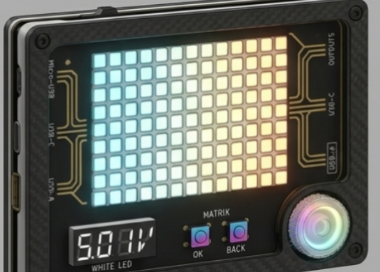
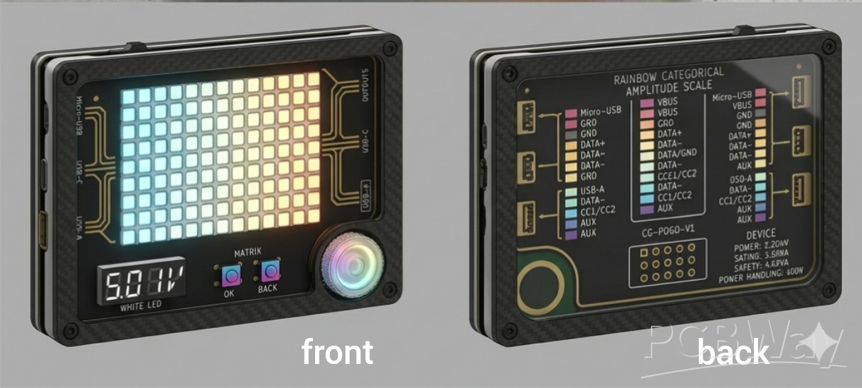
## 3. Physical Format & Canonical Port Mapping
The PCB footprint is locked into a compact **106\text{ mm} \times 80\text{ mm}** landscape envelope. The flanks feature six connectors arranged top-to-bottom on a uniform **20 mm slot spacing** to prevent physical cord over-mold collisions:
* **Left Flank (Inputs):** Slot 1: USB-C | Slot 2: USB-A | Slot 3: Micro-USB.
* **Right Flank (Outputs):** Slot 4: Micro-USB | Slot 5: USB-A | Slot 6: USB-C.
* **Interface Deck:** Features an integrated **0.56-inch Cool White 4-digit 7-segment telemetry block** driven over I^2C for low-noise voltage and current readouts. Context navigation is driven by two front switches (**OK** and **Back**) and a low-profile **knurled thumb-wheel rotary encoder** nested into the bottom-right chassis corner recess.
* **Persistent Power Gauge:** The rightmost column (**Column 16**) is permanently reserved as a dedicated charge meter, monitoring the supercapacitor via a tiny hardware voltage divider to provide power visibility across all operational modes.
## 4. Multi-Material Lamination Stackup
The Gradiator rejects the standard "PCB inside a plastic box" paradigm. It is structured as a five-material sandwich compressed together by four exposed, stainless steel M3 hex bolts:
1. **Optical Faceplate (Clear Acrylic/PETG):** Shields the display core and features a laser-etched technical HUD mask.
2. **Diffuser Gasket (Flexible White TPU):** An extruded honeycomb grid of 160 isolated cells that acts as an optical light-guide, converting harsh LED hot-spots into uniform, glowing square pixels while preventing vertical cross-row bleeding.
3. **The Circuit Engine (4-Layer PCB):** Holds the solid-state traces, finished in Matte Black with stark white ink and ENIG gold accents.
4. **Chassis Frame (Polycarbonate Carbon Fiber - PC-CF):** A 45-degree chamfered perimeter bumper that provides immense rigidity and completely absorbs cable insertion torque.
5. **Weighted Baseplate (Brushed Aluminum):** Provides a heavy, premium desk-anchor to prevent stiff cables from flipping or sliding the device across the workspace.
## 5. Circuit Design & Signal Integrity Engineering
* **Design for Manufacturability (DFM):** The board features a **100% Single-Sided SMT placement strategy** to streamline automated pick-and-place lines and maximize production yield rates. Passives have been heavily consolidated to reduce unique kitting lines.
* **The Inrush-Limited Power Loop:** The device features **no batteries**, making it perfectly drawer-safe. Operating energy is stored in a **10 Farad Supercapacitor Module**. A discrete current-limiting circuit using a commodity **2N3904 NPN transistor** caps inrush charging to a safe 450mA to prevent tripping host ports. A **TPS63021 buck-boost stage** guarantees a rock-solid, regulated 5.0V LED rail even as the capacitor voltage drains toward its system cutoff.
* **Scan Result Persistence: ** To eliminate the friction of brownouts, the ESP32-S3 utilizes its hardware conductor map, committed to NVS on every scan completion, so the last result is always recalled on boot automatically recalling the cached 32-byte binary conductor map at the next boot at a dimmed 60% brightness.
* **Trace Disciplines (KiCad 10 DRC Profile):** Universal paths (V_{BUS}, GND, D+, D-) are routed across large internal planes rated for 5A continuous pass-through current. Polished **ENIG Gold exposure is strictly restricted to these power tracks**. High-speed data lines are completely masked and routed as **controlled-impedance 90 \Omega differential pairs** over an unbroken Layer 2 reference plane to maintain strict signal integrity (Calculated via KiCad 10 coplanar waveguide formulas).
* **Metrology & Matrix Hardening:** Voltage and current metric collections bypass raw MCU ADC guesswork, utilizing a dedicated **INA226 I2C power monitor** sitting across a milliohm shunt. The 160 WS2812B-2020 pixels are isolated via **74AHCT125 logic-level buffers** to translate data lines cleanly from 3.3V to 5V, backed by a 330 \Omega edge-damping resistor and multi-point power injection.
## 6. Security Posture: Structural Privacy by Construction
The Cable Gradiator implements an explicit, hardware-gated privacy framework. The base unit is **structurally content-blind and incapable of reconstructing packet contents**, independent of firmware integrity. The high-impedance taps and analog multiplexers (CD74HC4067) lack the physical capture bandwidth or transceiver silicon required to decode multi-gigabit packets.
Advanced future metrics (such as Ethernet or protocol-aware logging) route exclusively to a rear **10-pin gold pogo bus**. Any mechanical engagement of this data transport completes a physical hardware path that energizes a **discrete, red warning LED**. This tell-tale sits entirely outside of MCU control—meaning compromised firmware cannot suppress or hide data-backpack engagement.
## 7. Appended Factory SMT Bill of Materials (BOM)
Optimized for **PCBWay 4-Layer Turnkey SMT Assembly**. Through-hole supercapacitors are designated as **Do Not Place (DNP)** for factory files; they ship in-box to eliminate wave-soldering overhead and are easily seated by the end-user.
| Block | Qty | Component Description | MPN | Package | LCSC Sourcing ID |
|---|---|---|---|---|---|
| **BRAIN** | 1 | ESP32-S3 Castellated SMD Module, 8MB Flash | ESP32-S3-MINI-1-N8 | LCC-56 Castellation | C2913202 |
| **DISPLAY** | 160 | Addressable High-Density Micro-RGB Pixels | WS2812B-2020 | SMD-2020 (2.2x2mm) | C965555 |
| | 1 | Logic Level Translator Buffer (3.3V to 5V) | 74AHCT125PW | TSSOP-14 | C7469 |
| **SCAN** | 2 | 16-Channel Analog Scanning Multiplexer | CD74HC4067SM96 | SSOP-24 | C98457 |
| | 32 | Mux Safety Series Current-Limit Resistors | 10 k$\Omega$ | 0402 | Consolidated Pool |
| **METROLOGY** | 1 | High-Precision I2C Power Monitor, 36V | INA226AIDGST | SOT-23-8 | C111190 |
| | 1 | Low-Loss Current Sense Shunt Resistor, 10m$\Omega$ | — | 2512 | C17070 |
| | 1 | Dedicated I2C Matrix 7-Segment Display Driver | HT16K33 | SOP-28 | C84673 |
| | 1 | 4-Digit 7-Segment Display Block, 0.56", Cool White | KEM5641AW | 12-Pin DIP (TH) | C225867 |
| **I/O FLANK** | 2 | USB-C Mid-Mount Receptacle, 16-Pin | TYPE-C-31-M-12 | SMD-16P | C165948 |
| | 2 | Micro-USB Receptacle, 5-Pin Right Angle | Molex 1050170001 | SMD-5P | C11831 |
| | 2 | USB-A Female Receptacle, 4-Pin Right Angle | AF90-Type | SMD-4P | C46396 |
| | 6 | High-Speed USB ESD Transient Protection Array | USBLC6-2SC6 | SOT-23-6 | C7519 |
| **POWER LOOP** | 1 | Wide-Input synchronous Buck Regulator (4.5-28V In) | TPS54302DDCR | SOT-23-6 | C311983 |
| | 1 | High-Efficiency Buck-Boost Storage Regulator | TPS63021DSJR | SON-10 | C131313 |
| | 2 | **[DNP]** Radial Supercapacitor, 10 Farad / 2.7V | BCAP0010 P270 T01 | Radial TH D12.5xL30 | DigiKey: 565-1022-ND |
| | 1 | Charge Limiter Transistor Circuit | 2N3904 | SOT-23 | C20526 |
| | 1 | Branch Protection Self-Resetting PTC Polyfuse | MF-MSMF050-2 | 1812 | C210348 |
| **USER HMI** | 1 | Right-Angle Rotary Encoder with Integrated Push | EC11E15204AK | TH R/A Edge-Mount | C255523-RA |
| | 2 | Contextual UI Tactile Click Switches (OK / Cancel) | Alps SKRPACE010 | SMD 4-Pin Flat | C139797 |
| | 1 | Master Power Break Slide Switch | MSK-12C02 | SMD Border Mount | C431541 |
## 8. Declared Limitations
1. **Inline SuperSpeed:** The device does not carry a live SuperSpeed link inline; inline USB-C passes operate at USB 2.0 class to preserve pure signal integrity without adding trace routing distortion.
2. **Data Sensing is Physical-Layer Only:** Displays presence, activity, timing, and line transitions—never packet text contents.
3. **No E-Marker Readout in the Base Unit:** Power delivery wattage certification readouts are reserved for the upcoming pogo bus backpack module tier.
—
There you have it folks! I give you the EPIC Cable Gradiator by EPIC WIN Productions Media.
Cable Gradiator
Project images are for reference only. Actual production is based on the manufacturing files on the project page.
Please review the designer's notes (e.g., PCB thickness) and select the appropriate options.
PCBWay is not responsible
for issues caused by unsuitable parameter selections.
For more important ordering information, please refer to
Read More


Raspberry Pi 5 7 Inch Touch Screen IPS 1024x600 HD LCD HDMI-compatible Display for RPI 4B 3B+ OPI 5 AIDA64 PC Secondary Screen(Without Speaker)
BUY NOW


- Comments(5)
- Likes(2)
- 2 USER VOTES
- YOUR VOTE 0.00 0.00

-
2design
-
2usability
-
2creativity
-
2content

-
10design
-
9usability
-
10creativity
-
9content
More by B Harris
-
Programmable Mist Maker - XIAO / QT PY Extension
1150 2 1 -
RadioHAT - Raspberry Pi radio development platform
960 0 2 -
-
-
-
-
ARPS-2 – Arduino-Compatible Robot Project Shield for Arduino UNO
3382 0 6 -
A Compact Charging Breakout Board For Waveshare ESP32-C3
4001 3 8 -
AI-driven LoRa & LLM-enabled Kiosk & Food Delivery System
4389 2 2


