


|
|
STM32F103C8T6STMicroelectronics
|
x 1 | |
|
|
HLK-5M03HI-LINK
|
x 1 | |
|
|
T1635-600G-TRSTMicroelectronics
|
x 1 | |
|
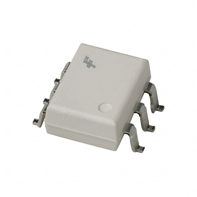
MOC3053SMonsemi
|
x 1 | |
|
|
X49SM8MSD2SCXYC
|
x 1 | |
|
EL817S1(C)(TU)-FGEverlight Electronics Co Ltd
|
x 1 |
|
|
KiCad 10.0KiCad
|
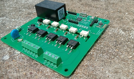
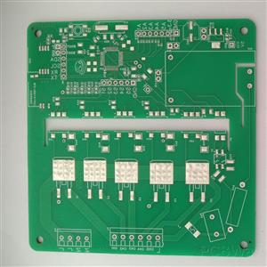
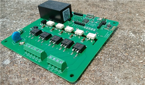
5 Channel AC Dimmer and Switch Module with STM32
Introduction
A high-voltage circuit capable of switching and smoothly dimming up to five independent 220V AC channels. Driven by an onboard STM32F103C8T6 microcontroller, the module acts as a versatile hardware interface that can operate completely independently with physical inputs (switches/potentiometer) or function as a modular peripheral controlled by an external master system.
Key Features:-
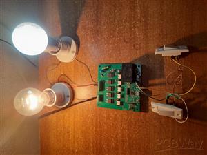
- 5 Independent Channels: Control up to five separate AC loads from a single board.
- Dimming & Speed Control: Instead of just On/Off Switch,Sliders(or rotary switch) can be used to smoothly dim lights or adjust ceiling fan speeds.
- Electric shock proof: The physical switches connect to the STM32F103C8T6 using a logic-level 3.3V DC signal.This completely eliminates the risk of electric shock.It is safe to operate the switches even with wet hands.
- High Load Capacity: Uses 16A, 600V snubberless TRIACs to handle substantial household Appliances loads.
- Expansion Ready: Broken out headers for I2C, UART, and Analog pins to easily add ESP8266/ESP32 modules for wireless communication, environmental sensors, or local displays.
- Self-Powered: An onboard AC-to-DC step-down module means no external power bricks are required.
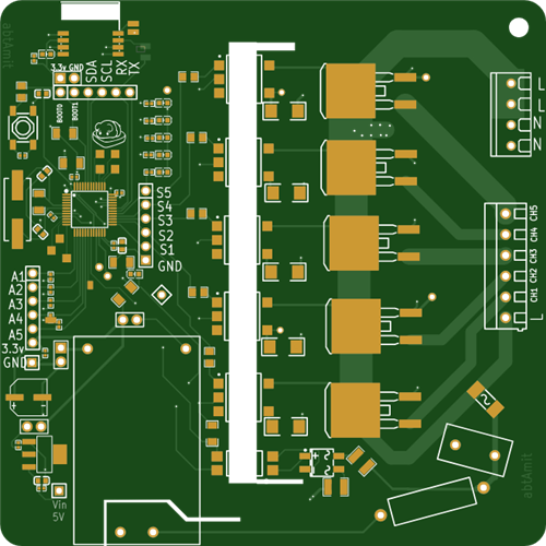
Hardware Architecture and Schematic Breakdown:-
1. STM32F103C8T6 Microcontroller
At the core is the STM32F103C8T6. While an 8-bit MCU could handle one or two dimming channels, managing five simultaneous channels requires precise, microsecond-level timing. The STM32's advanced hardware timers calculate the exact firing delay for each TRIAC independently after every AC zero-cross event, ensuring smooth fading without tying up the main processing loop.
2. Zero-Cross Detection (ZCD) Circuit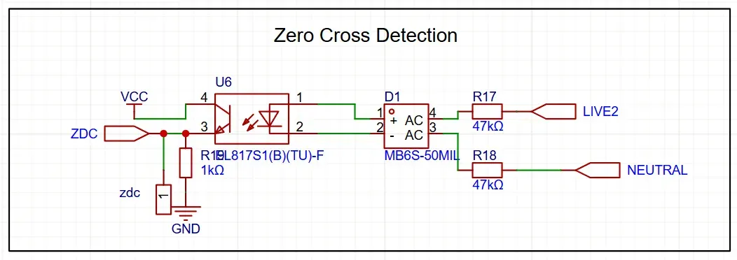
To dim an AC load, the microcontroller must know exactly when the AC sine wave crosses zero volts.
The mains AC is converted to pulsating DC using an MB6S bridge rectifier.
The pulsating DC passes through high-wattage current-limiting resistors (47kΩ) into an EL817 optocoupler.
Every time the AC voltage drops to zero, the optocoupler briefly turns off, sending a precise pulse to the STM32's ZCD pin. This pulse acts as the metronome for the entire dimming operation.
3. High-Voltage Control and Isolation
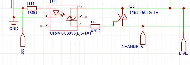
Optoisolation: The MCU is isolated from the mains voltage using MOC3053 random-phase optocouplers. These are triggered by a low 5mA current, safely driven directly from the STM32's PB12, PB13, PB14, PB15, and PA8 pins.
Power Switching: It has high-power (16-Amp) T1635 snubberless triacs that handle the physical switching of the AC load, driven by the optocouplers through 470Ω gate resistors and A1 connects directly to live and A2 connects to the channel terminal for connecting appliances.
4. Power Supply and Noise Filtering
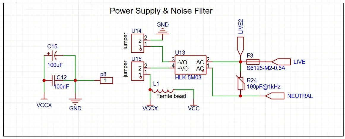
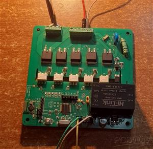
An HLK-5M03 step-down module is used to convert 220V AC directly to the 3.3V DC needed for the MCU and logic components.
Input Protection: The AC input line has a fuse (0.5A) and a mov 10D471 to protect the board against short circuits or catastrophic load failures.
Noise Filter: The 3.3v side it uses Pi Filter that has 100uF, 100nF capacitor and 150mΩ 1A 60Ω@100MHz Ferrite Bead and 10uF,100nF capacitor after Ferrite Bead to suppress the noise.
5. Interfaces & Connectivity
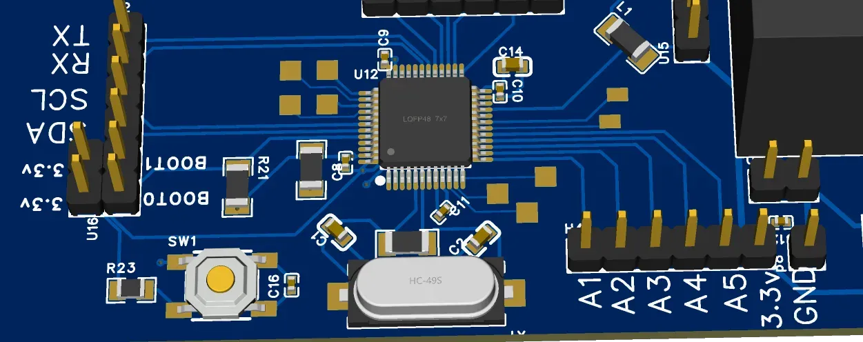
Analog/Digital Inputs: Pins A1 to A5 are for controlling the channels, you can use Switches to turn ON/OFF or rotary switches can be used for dimming purpose.
UART and I2C: PA9 (TX), PA10 (RX) and PB6 (SCL) and PB7 (SDA) are exposed for debugging, serial firmware flashing or to receive digital dimming commands.
How It Works
1. Syncing: The ZCD circuit detects the AC zero-crossing point (100 times a second for 50Hz mains) and triggers an interrupt on the STM32.
2. Calculating Delay: Depending on the desired brightness level (0-100%), the STM32 calculates a delay. For maximum brightness, the delay is nearly 0ms. For 50% brightness, the delay is exactly half of the AC half-cycle (e.g., 5ms for a 50Hz system).
3. Polling: The STM32 uses Timer ISR to check if it is the time to turn on any of five channels.
4. Firing: Once the calculated delay for a specific channel has elapsed, the STM32 sends a brief HIGH signal to the corresponding MOC3053 optoisolator. The optoisolator triggers the gate of the T1635 TRIAC, allowing AC current to flow to the connected load for the remainder of that half-cycle. This process repeats continuously, resulting in a smoothly dimmed output.
Demonstration video: https://youtube.com/shorts/1uroGZGKNSg?si=-Uw9idMF3iC2jh1L
*used esp8266 with this module for wireless control
5 Channel AC Dimmer and Switch Module with STM32
Project images are for reference only. Actual production is based on the manufacturing files on the project page.
Please review the designer's notes (e.g., PCB thickness) and select the appropriate options.
PCBWay is not responsible
for issues caused by unsuitable parameter selections.
For more important ordering information, please refer to
Read More


Raspberry Pi 5 7 Inch Touch Screen IPS 1024x600 HD LCD HDMI-compatible Display for RPI 4B 3B+ OPI 5 AIDA64 PC Secondary Screen(Without Speaker)
BUY NOW


- Comments(0)
- Likes(2)
- 1 USER VOTES
- YOUR VOTE 0.00 0.00
-
10design
-
10usability
-
10creativity
-
10content
More by Amit Kumar
-
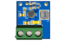 Miniature 3.3v buck Converter with TPS62130A
FeaturesUltra-Compact Footprint: Extremely small form factor measuring just 17x19mm, which reduces t...
Miniature 3.3v buck Converter with TPS62130A
FeaturesUltra-Compact Footprint: Extremely small form factor measuring just 17x19mm, which reduces t...
-
 5 Channel AC Dimmer and Switch Module with STM32
IntroductionA high-voltage circuit capable of switching and smoothly dimming up to five independent ...
5 Channel AC Dimmer and Switch Module with STM32
IntroductionA high-voltage circuit capable of switching and smoothly dimming up to five independent ...
-
 Smart Home Energy Monitor
In this project, I have built an advanced, distributed Home Automation System based on the energy-ef...
Smart Home Energy Monitor
In this project, I have built an advanced, distributed Home Automation System based on the energy-ef...
-
Programmable Mist Maker - XIAO / QT PY Extension
1055 2 1 -
RadioHAT - Raspberry Pi radio development platform
850 0 2 -
-
-
-
-
ARPS-2 – Arduino-Compatible Robot Project Shield for Arduino UNO
3317 0 6 -
A Compact Charging Breakout Board For Waveshare ESP32-C3
3922 3 8 -
AI-driven LoRa & LLM-enabled Kiosk & Food Delivery System
4310 2 2


