Summary: A beginners guide to setting up i2c sensors and devices on a Raspberry Pi Pico using CircuitPython
I have several i2c devices which I use on the Raspberry Pi computers and program then in Python. Now I have a Raspberry Pi Pico RP2040 microcontroller board, I wanted to try my i2c devices out on the Pico. I am using Adafruit's CircuitPython as there are many libraries already available for many electronic devices which makes it a lot easier.
As Circuit Python is designed for Micro Controllers with low memory the libraries are more basic than the ones use for Python on desktop computers. So common libraries like numpy, matplotlib, scipy and Pillow are not available though there is a ulab which is like a cut down version of numpy.
To install Circuit Python you download the adafruits .uf2 firmware file from circuitpython.org/downloads . Connect the Pico to a computer with the bootsel button pressed to put it in USB mode. Drop the .utf file into the Pico's drive. Then disconnect the Pico. When you reconnect it CircuitPython will be ready. Then using Thonny or Mu python editors on a PC or Raspberry Pi , you can access the Pico and run your code. When you are done, disconnect the Pico from the computers USB, then when it next has power your code will run.
The main concept is your program is called code.py, this will run automatically when the micro controller has power. Any additional libraries are manually copied to the root or lib folder on the PIco. As soon as you save the file it will run, not always useful when you are developing a program having to stop it before saving it again. Your program can also be called code.txt, main.txt and main.py but code.py is the standard used name. To run a script with a different name you will need to add a reference to code.py or main.py to import and run the myscript,py file. If you are using Thonny then you can run the myscript.py from the tool bar but you have to stop code.py from running first. This is only useful for testing purposes. If there is a short break with no programs running then code.py will start running again which can be a bit of pain while testing new scripts.
Adafruits supply the libraries and example files for many devices and sensors so you should be able to find the code to get you started.

The Raspberry Pi Pico has 2 x I2C peripherals, these can be accessed across 6 sets of GPIO pins per peripheral. This means you can easily connect 12 devices without needing any daisy chaining unlike the Raspberry Pi main boards that only have 1 set available as standard.
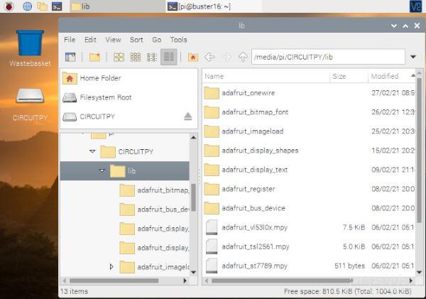
For i2c to work you will need the library folders of adafruit_bus_device and adafruit_register in the lib or root folder on the Pico.
The libraries can be downloaded to your computer from circuitpython.org/libraries and then transferred to the Pico.
For your i2c program you will need to import the libraries board and busio. Your code will use the line i2c = busio.I2C(board.SCL, board.SDA) to create a I2C object but this doesn't work on a PIco.
For the Pico you will need to replace the SDA and SCL with the Pin numbers. These are different for each micro controller so you can use some programs from the Adafruit website to view the GPIO pin names, the i2c SDA and SCL pins.
board.GP0
board.GP1
board.GP2
board.GP3
board.GP4
board.GP5
board.GP6
board.GP7
board.GP8
board.GP9
board.GP10
board.GP11
board.GP12
board.GP13
board.GP14
board.GP15
board.GP16
board.GP17
board.GP18
board.GP19
board.GP20
board.GP21
board.GP22
board.GP25 board.LED
board.A0 board.GP26 board.GP26_A0
board.A1 board.GP27 board.GP27_A1
board.A2 board.GP28 board.GP28_A2
or
SCL pin: board.GP1 SDA pin: board.GP0
SCL pin: board.GP3 SDA pin: board.GP2
SCL pin: board.GP5 SDA pin: board.GP4
SCL pin: board.GP7 SDA pin: board.GP6
SCL pin: board.GP9 SDA pin: board.GP8
SCL pin: board.GP11 SDA pin: board.GP10
SCL pin: board.GP13 SDA pin: board.GP12
SCL pin: board.GP15 SDA pin: board.GP14
SCL pin: board.GP21 SDA pin: board.GP20
SCL pin: board.GP27_A1 SDA pin: board.GP26_A0
The code for these list are at learn.adafruit.com/circuitpython-essentials/circuitpython-pins-and-modules and learn.adafruit.com/circuitpython-essentials/circuitpython-i2c
So depending on what pins you use the code would be for example i2c = busio.I2C(board.GP1, board.GP0)
if you are using the first two GPIO pins on the left of the Pico board.
The next line will be assigning the i2c object to the device library. Adafruits will have their sensors address coded into the library. Often the sensor will be the same on different manufactures boards but you may need to change this.
In this example adafruits library uses address 0x75 but I needed 0x76 so you can make the change at this point.
i2c = busio.I2C(board.GP1, board.GP0)
sensor = adafruit_bme680.Adafruit_BME680_I2C(i2c,address=0x76)
That's the basics to for an i2c connection for the Raspberry Pi Pico using Circuit Python.
I will go through how to setup an i2c device with Circuit python on the Pico. This will be for
VL53L0X - Time of Flight distance sensor
How to setup these devices can be found at the link at the bottom of this guide.
TSL2561 - Ambient Light Sensor
BME680 - Air Quality, Pressure, Humidity and Temperature sensor
AS7282 - 6 Channel Spectral Sensor
These programs will all use a SPI connected 240 x 240 lcd display to show the results.
To use the i2c sensor, you will need the board and busio libraries. The time library is useful for sleep and you will also need the libraries to run the SPI LCD display. terminalio, displayio, adafruit_st7789, adafruit_display_text. As the standard font is small and blocky these scripts will also use a free font Sans-SerifPro-Bold so the adafruit_bitmap_font library will also be needed. These are available in a download by following the link at the base of this article.
Libraries Required:
board
busio
terminalio
displayio
adafruit_st7789 - to use the display in the examples
adafruit_display_text
adafruit_bitmap_font
adafruit_vl53l0x - to use the vl53l0x ToF sensor
also the Sans-SerifPro-Bold fonts in size 20 & 40
From the Adafruit Libraries that you downloaded to your computer, copy the above libraries to the lib folder on the CIRCUITPY drive of

The first sensor will a be the VL03L0X ToF distance measuring laser. This is simple to use and has one adjustable setting for accuracy.
The sensor needs 4 connections. A 3v supply, Ground, SDA and SCL i2c connections. For this program I have used the last two pins on the left side from the i2c 1 connections. GP14 (SDA) and GP15 (SCL). The 3v supply comes from the 5th pin on the right (3v3 Out)
For this script start by importing all the required libraries.
import time
import board
import busio
import adafruit_vl53l0x #ToF sensor
from adafruit_bitmap_font import bitmap_font
import terminalio
import displayio
from adafruit_display_text import label
from adafruit_st7789 import ST7789 #display
next is a variable to allow an offset if the sensor is mounted in a case to minus the depth of the case from the measured distance.
distoffset = 0 #case offset in mm
This section sets up the SPi device for connection to the display and the 240 x 240 pixel display.
#display setup
displayio.release_displays()
spi = busio.SPI(board.GP18, board.GP19)
tft_cs = board.GP17
tft_dc = board.GP16
display_bus = displayio.FourWire(spi, command=tft_dc, chip_select=tft_cs)
display = ST7789(display_bus, width=240, height=240, rowstart=80, rotation=180)
Now the i2c setup is made with the SDA wire as GP15 and the SCL at GP14
i2c = busio.I2C(board.GP15, board.GP14)
vl53 = adafruit_vl53l0x.VL53L0X(i2c, address=0x29)
The VL53L0X has an i2c address of 29 which has also been set in case it doesn't match what is in the library for the VL53L0X board.
Next a few functions will be setup. The first one is to set the measuring accuracy of the sensor. This takes 1 argument of the time allowed to measure which is in milliseconds. 33 is the default accuracy. More accurate results will be acheived with a setting of 200 or higher depending on how quick you need the results.
def vl53accuracy(self):
"""Change Distance Accuracy Setting"""
#give time in ms ie 33 for default
vl53.measurement_timing_budget = self * 1000
The next function gets the latest measurement from the sensor. This particular sensor can measure up to 2 meters in ideal conditions but in general use it is about 1.2 meters. If there is no object in range the results will be over 8000. This function will return "Out of Range" when this happens otherwise give a string of the measurement minus any offset defined at the top of the script.
def vl53dist():
a = vl53.range
if a > 5000:
return "Out of Range"
else:
return vl53.range - distoffset
The next function does the work by getting the latest results and then drawing the results on the screen just using text.
def dispvl53(acc, cali):
global distoffset
if type(acc) == int:
if acc > 0:
vl53accuracy(acc)
else:
vl53accuracy(33)
if type(cali) == int:
distoffset = cali
font20 = bitmap_font.load_font("/SerifPro-Bold-20.pcf")
font40 = bitmap_font.load_font("/SerifPro-Bold-40.pcf")
text_group = displayio.Group(max_size=10, scale=1, x=5, y=10)
text=str(vl53dist()) #get reading
dist = label.Label(font40, text=text, color=0xFFFF00, x=0, y=120)
text_group.append(dist) # Subgroup for text scaling
title = label.Label(font40, text="Distance\nmm:", color=0xFFAA00, x=5, y=15)
text_group.append(title)
display.show(text_group)
The first few lines check that the entries for acc & cali are numbers.
Then the 2 sizes of fonts are loaded ready for use.
text_group is used to zone an area of the display ready to have text added.
Label then takes some text and positions it in the group zone
The display group works like a list so you can append new elements as long as it doesn't exceed the max_size of elements. In this case it is 10.
Once all the elements are in place then use display.show to show the image.
The next section is used when the script is run rather than called from another script.
def main():
while True:
dispvl53(33,0) #accurracy, offset
time.sleep(0.3) #screen update
if __name__ == "__main__":
main()
If you save this file as code.py and save it to the Pico's root folder it will automatically run when the Pico has power.
further device i2c device setup and examples at


