By Hesam Moshiri, Anson Bao
Features:
Identify a fake Lithium-Ion/Lithium-Polymer/NiCd/NiMH battery
Adjustable constant current load (can also be modified by the user)
Capable of measuring the capacity of almost any kind of battery (below 5V)
Easy to solder, build, and use, even for beginners (all components are Dip)
An LCD user interface
Specifications:
Board Supply: 7V to 9V(Max)
Battery Input: 0-5V(max) – no reverse polarity
Constant Current Load: 37mA to 540mA(max) – 16 Steps – can be modified by the user
The true measurement of a battery’s capacity is essential for many scenarios. A capacity measurement device can solve the problem of spotting fake batteries as well. Nowadays fake Lithium and NiMH batteries are everywhere which don’t handle their advertised capacities. Sometimes it is difficult to distinguish between a real and a fake battery. This problem exists in the spare batteries market, such as cell phone batteries. Furthermore, in many scenarios, it is essential to determine the capacity of a second-hand battery (for instance a laptop battery). In this article, we will learn to build a battery capacity measurement circuit using the famous Arduino-Nano board. I’ve designed the PCB board for dip components. So even beginners can solder and use the device.
1: Circuit Analysis
Figure 1 shows the schematic diagram of the device. The core of the circuit is an Arduino-Nano board. 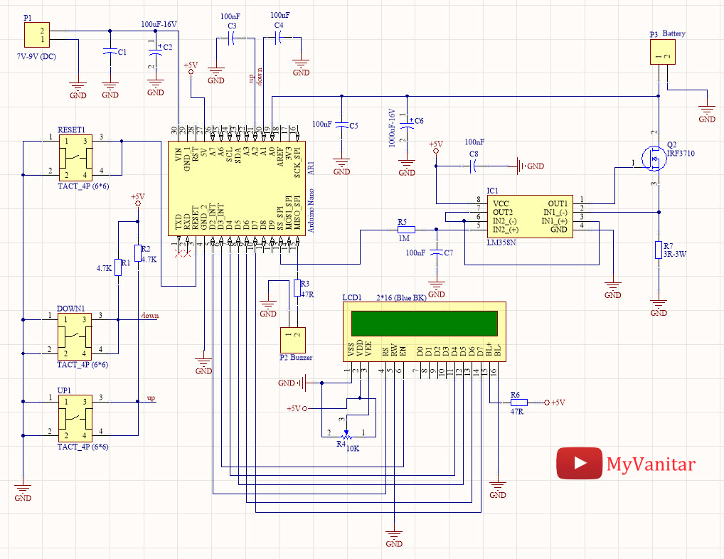
Figure 1
Schematic diagram of the battery capacity measurement device
IC1 is an LM358 [1] chip which contains two operational amplifiers. R5 and C7 build a low pass filter which converts the PWM pulse to a DC voltage. The frequency of the PWM is around 500Hz. I used a Siglent SDS1104X-E oscilloscope to examine the PWM and filter’s behavior. I connected the CH1 to the PWM output (Arduino-D10) and CH2 to the filter’s output (Figure 2). You can even examine the filter’s frequency response and its cut-off frequency “in practice” by the bode plot, which is one of the nice introduced features of the SDS1104X-E. 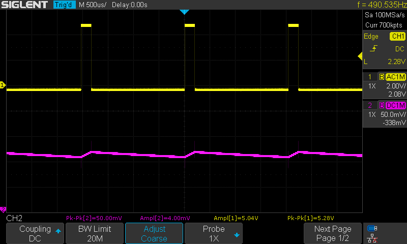
Figure 2
The PWM signal (CH1: 2V/div) and the result after passing through the R5-C7 RC filter (CH2: 50mV/div)
R5 is a 1M resistor which hugely limits the current, however, the output of the filter passes through an opamp (the second opamp of IC1), in a voltage follower configuration. The first opamp of the IC1, R7, and Q2 build a constant current load circuit. So far, we have built a PWM controllable constant current load.
A 2*16 LCD is used as a user interface which makes the controlling/adjustments easy. R4 potentiometer sets the LCD contrast. R6 limits the backlight current. P2 is a 2 pins Molex connector that is used to connect a 5V buzzer. R1 and R2 are pull-up resistors for the tactile switches. C3 and C4 are used to debounce the push-buttons. C1 and C1 are used to filter the circuit supply voltage. C5 and C6 are used to filter out the constant current load circuit noises to not to degrade the ADC conversion performance. R7 acts as a load for the Q2 MOSFET.
1-1: What is a constant current DC load?
A constant current load is a circuit that always draws a constant amount of current, even if the applied input voltage varies. For example, if we connect the constant current load to a power supply and set the current on 250mA, the current draw will not change even if the input voltage is 5V or 12V or whatever. This feature of the constant current load circuit allows us to build the battery capacity measurement device. If we use a simple resistor as a load to measure the battery capacity, as the battery voltage decrease, the current also decreases which make the calculations complex and inaccurate.
2: PCB Board
Figure 3 shows the designed PCB layout of the circuit. Both sides of the board are used to mount the components.
When I intend to design a Schematic/PCB, I always use the SamacSys component libraries, because these libraries follow industrial IPC standards and all are free. I used these libraries for IC1 [2], Q2 [3], and even I could find the Arduino-Nano (AR1) [4] library which saved a lot from the designing time. I use the Altium Designer CAD software, so I used the Altium plugin to install the components libraries [5]. Figure 4 shows the selected components. 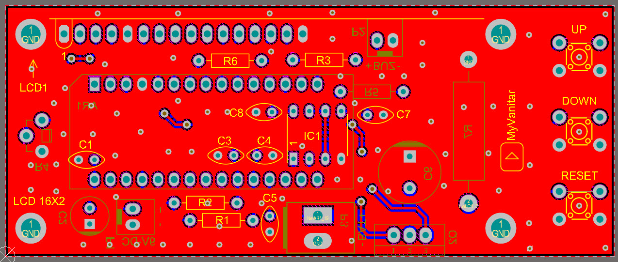
Figure 3
The PCB board of the battery capacity measurement circuit
When I intend to design a Schematic/PCB, I always use the SamacSys component libraries, because these libraries follow industrial IPC standards and all are free. I used these libraries for IC1 [2], Q2 [3], and even I could find the Arduino-Nano (AR1) [4] library which saved a lot from the designing time. I use the Altium Designer CAD software, so I used the Altium plugin to install the components libraries [5]. Figure 4 shows the selected components. 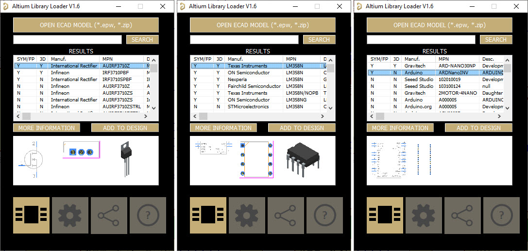
Figure 4
Installed components from the SamacSys Altium plugin
The PCB board is slightly bigger than a 2*16 LCD to fit the three tactile push-buttons. Figures 5, 6, and 7 show 3D views of the board. 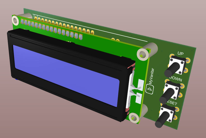
Figure 5
A 3D view of the assembled PCB board (TOP)
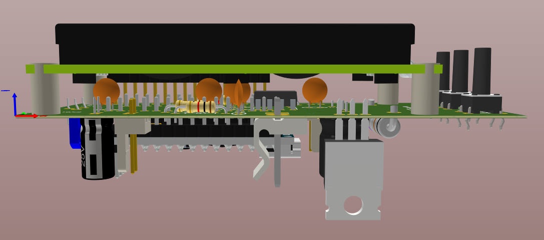
Figure 6
A 3D view of the assembled PCB board (Side) 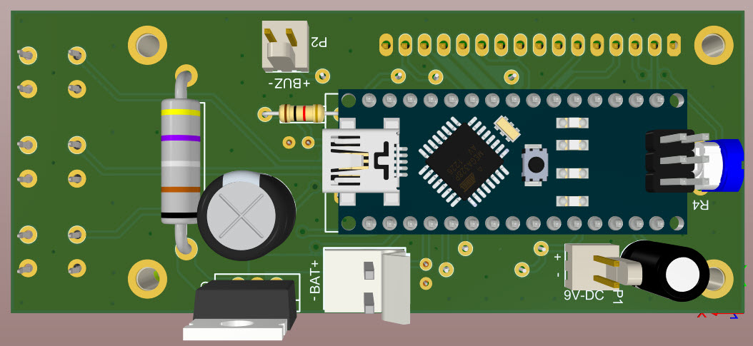
Figure 7
A 3D view of the assembled PCB board (Bottom)
3: Assembly and Test
I used a semi-homemade PCB board to build a fast prototype and test the circuit. Figure 8 shows a picture of the board. You don’t need to follow me, just order the PCB to a professional PCB fabrication company and build the device. You should use a standing potentiometer type for the R4 which allows you to adjust the LCD contrast from the side of the board.

Figure 8
A picture of the first prototype, on a semi-homemade PCB board
After soldering the components and preparing the test conditions, we are ready to test our circuit. Don’t forget to mount a big heatsink on the MOSFET (Q2).
I selected R7 to be a 3-ohm resistor. This allows us to generate constant currents up to 750mA, but in the code, I set the maximum current to somewhere around 500mA which is enough for our purpose. Lowering the resistor value (to for example 1.5-ohm) can make higher currents, however, you have to use a more powerful resistor and modify the Arduino code. Figure 9 shows the board and its external wirings.
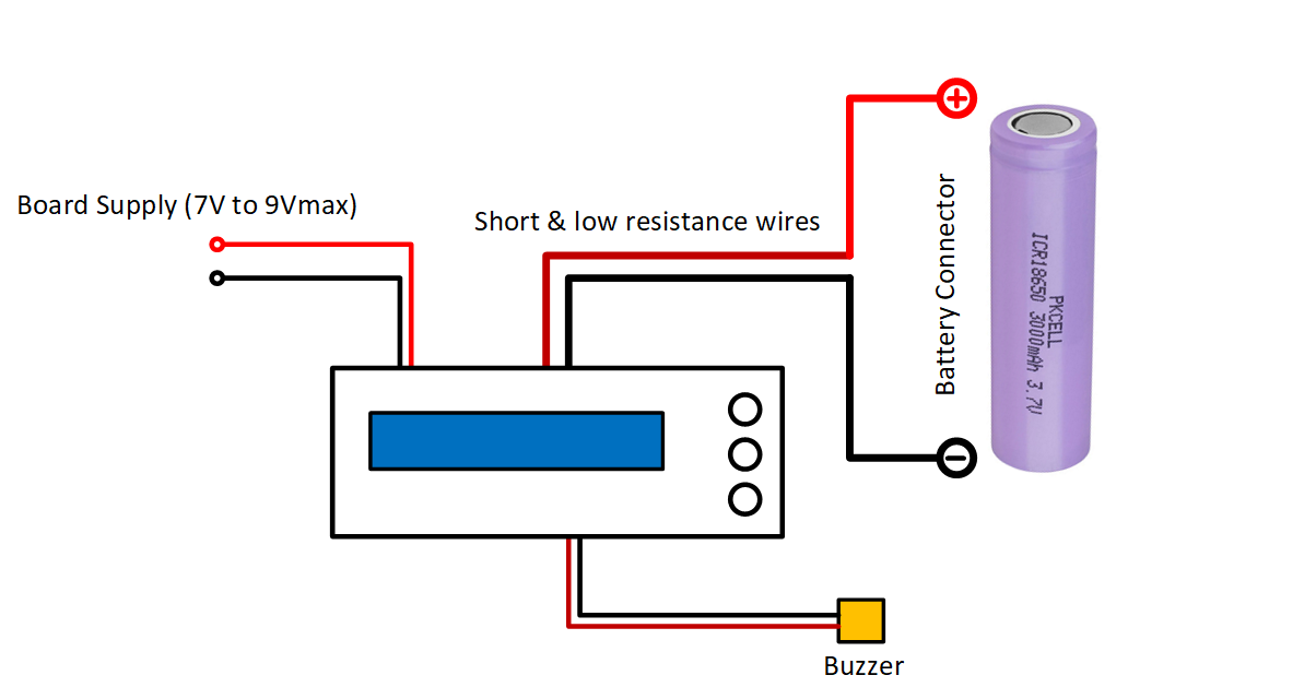
Figure 9
Wiring of the battery capacity measurement device
Prepare a voltage of something around 7V to 9V to the supply input. I have used the Arduino board’s regulator to make the +5V rail. Therefore, never apply a voltage higher than 9V to the supply input, otherwise, you might damage the regulator chip.
The board will be powered-up and you should see a text on the LCD, the same as figure 10. If you use a blue backlight 2*16 LCD, the circuit will consume around 75mA. 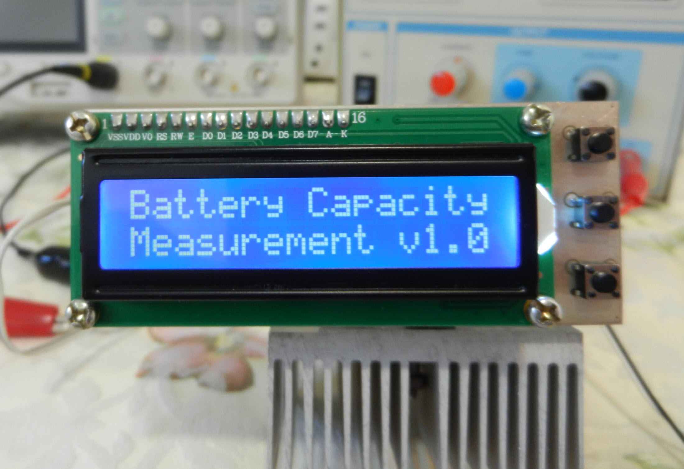
Figure 10
Correct circuit power-up indication on the LCD
After around 3 seconds, the text will be cleared up and in the next screen, you can adjust the constant current value by the up/down push buttons (Figure 11).
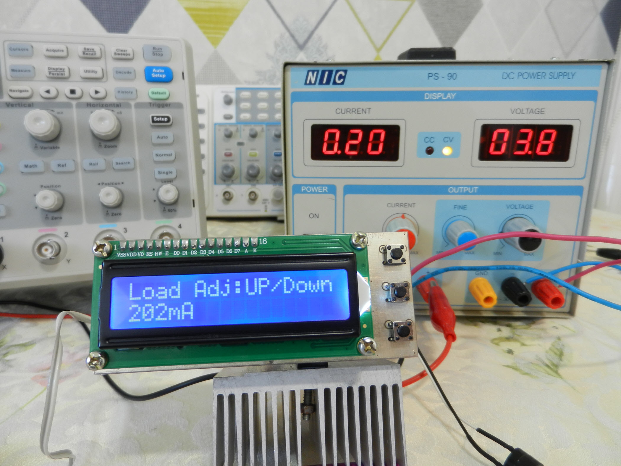
Figure 11
The constant current load adjustment by Up/Down push-buttons
Before connecting a battery to the device and measuring its capacity, you can examine the circuit using a power supply. For this purpose, you should connect the P3 connector to the power supply.
Important: Never apply any voltage higher than 5V, or in reverse polarity, to the battery input, otherwise you will permanently damage the Arduino’s digital to converter pin.
Set your desired current limit (for instance 100mA) and play with your power supply voltage (stay below 5V). As you can see with any input voltage, the current flow remains intact. That’s exactly what we want! (Figure 12).

Figure 12
The current flow remains constant even in front of voltage variations (tested with 4.3V and 2.4V inputs)
The third push-button is Reset. It means it simply restarts the board. It is useful when you plan to re-initiate the procedure to test a different buttery.
Anyway, now you are sure that your device works flawlessly. You can disconnect the power supply and connect your battery to the battery input and set your desired current limit.
To start my own test, I selected a brand new 8,800mA rated lithium-ion battery (Figure 13). It looks like a fantastic rate, isn't it?! But I cannot believe this somehow :-), so let’s test it.
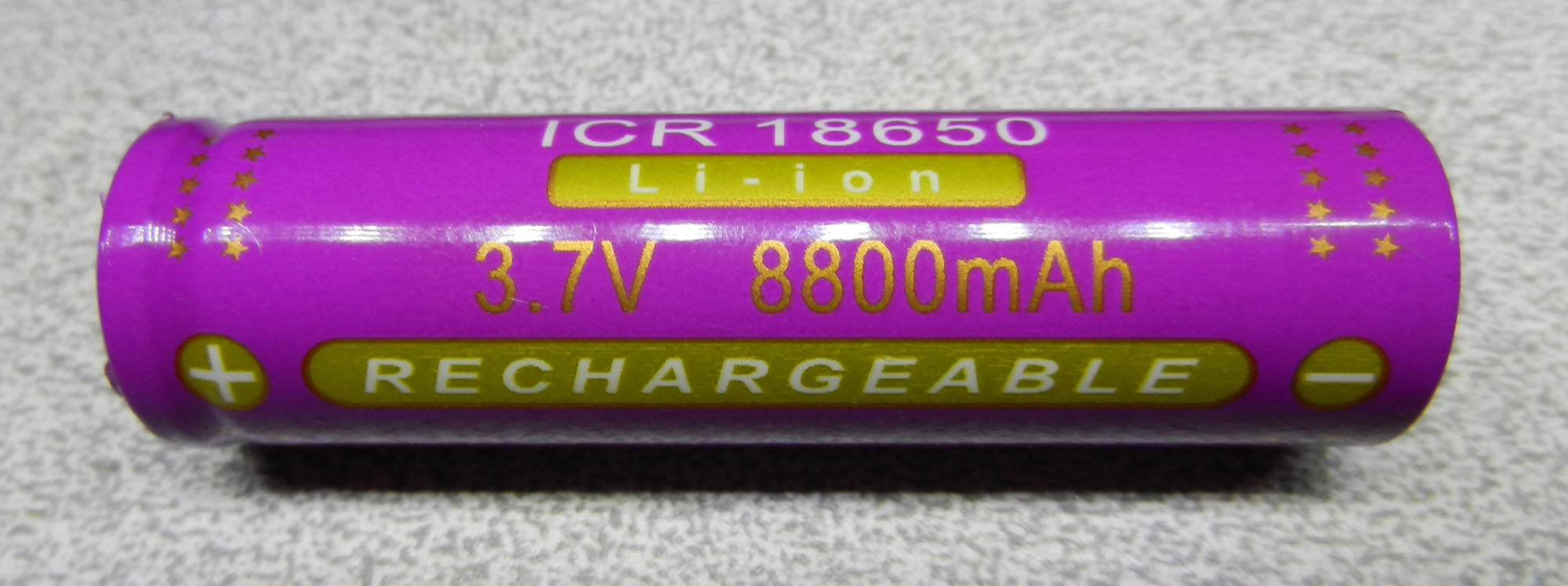
Figure 13
An 8,800mA rated lithium-ion battery, real or fake?!
Before connecting the lithium battery to the board, we must charge it, so please prepare a fixed 4.20V (500mA CC limit or lower) with your power supply (For instance, by using the variable switching power supply in the previous article) and charge the battery till the current flow reaches to a low level. Don’t charge an unknown battery with high currents, because we are not sure about its real capacity! High charging currents might explode the battery! Be careful. As a result, I followed this procedure and our 8,800mA battery is ready for capacity measurement.
I used a battery holder to connect the battery to the board. Make sure to use thick and short wires which introduce low resistance because power dissipation in wires causes voltage drop and inaccuracy.
Let’s set the current to 500mA and long-pressed the “UP” button. Then you should hear a beep and the procedure starts (Figure 14). I’ve set the cut-off voltage (low battery threshold) to 3.2V. You can modify this threshold in the code if you like.
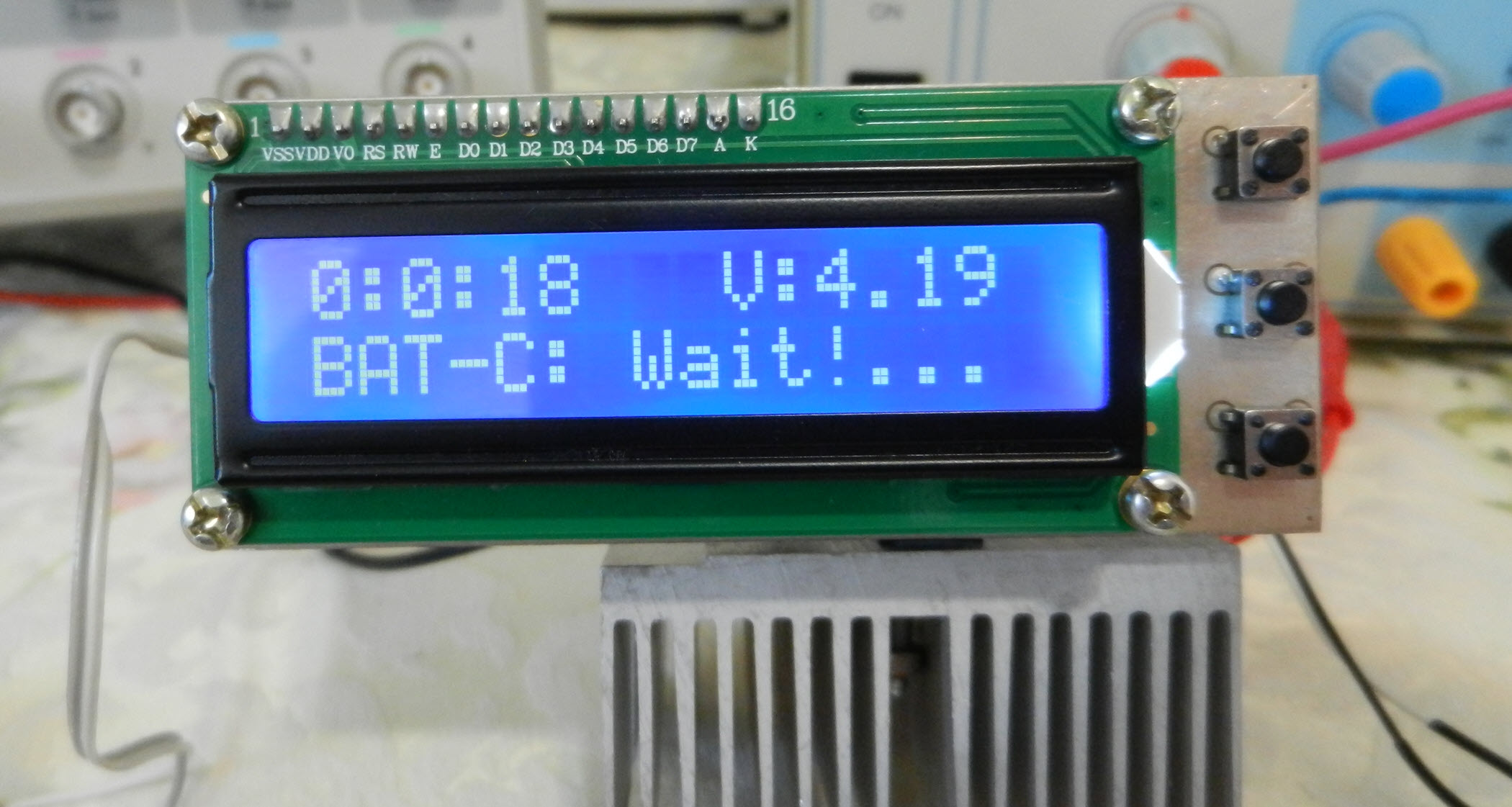
Figure 14
Battery capacity calculation procedure
Basically we should calculate the “life-time” of the battery before its voltage reaches the low-level threshold. Figure 15 shows the time when the device disconnects the DC load from the battery (3.2V) and calculations are made. The device also generates two long beeps to indicate the end of the procedure. As you can see in the LCD screen, the true battery capacity is 1,190mAh which is far from the claimed capacity! You can follow the same procedure to test any battery (lower than 5V).
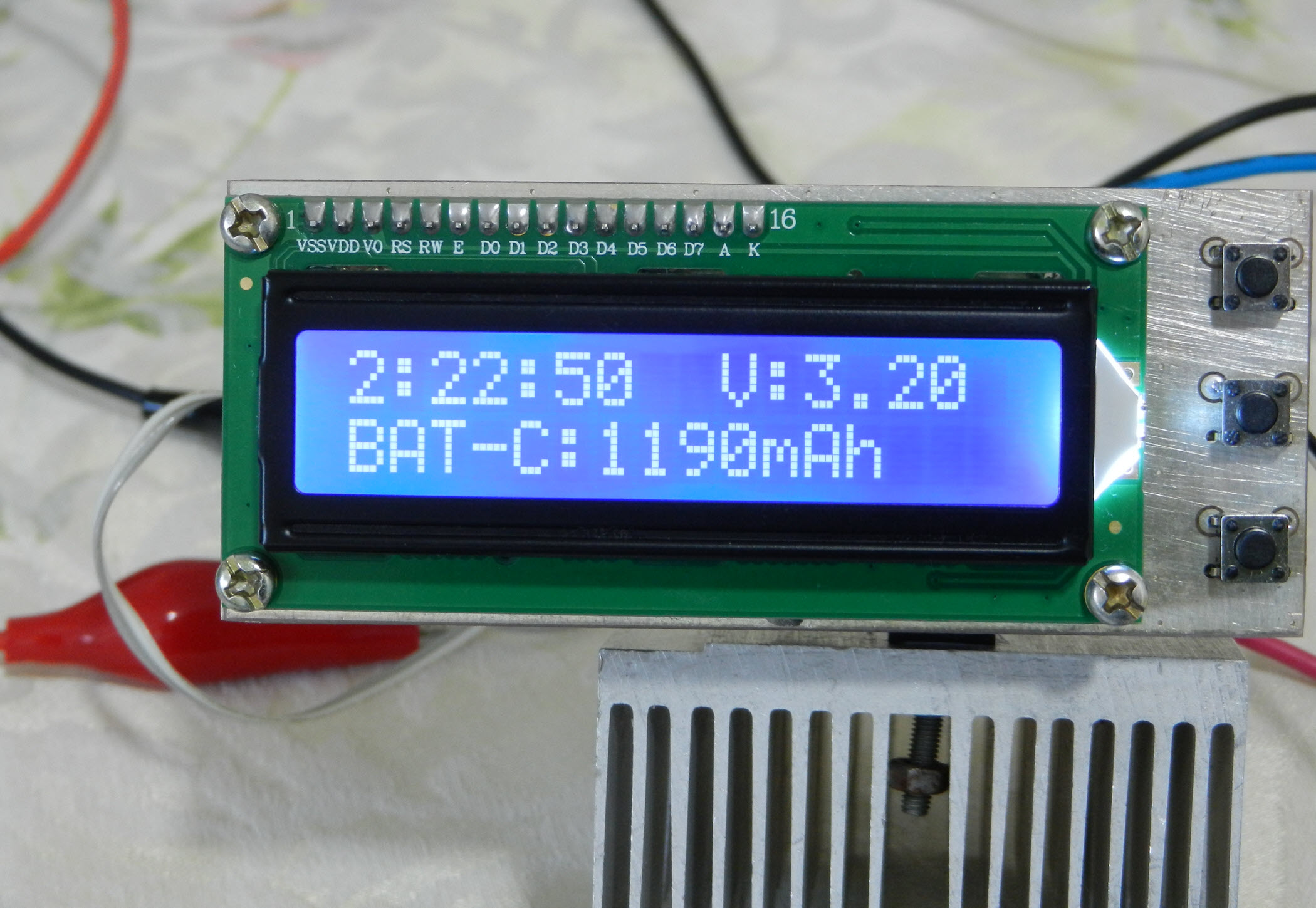
Figure 15
The true calculated capacity of the 8.800mA rated lithium-ion battery
Figure 16 shows the bill of materials for this circuit.
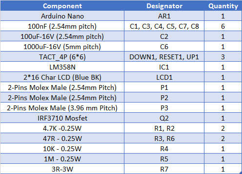
Figure 16
Bill of materials
If you want to build this device, you can download the Gerber files or directly order the PCB to be fabricated for you with the highest quality.
References
[1]: https://www.onsemi.com/pub/Collateral/LM358-D.PDF
[2]: https://componentsearchengine.com/part.php?partID=671517
[3]: https://componentsearchengine.com/part.php?partID=617283
[4]: https://componentsearchengine.com/part.php?partID=368895
[5]: https://www.samacsys.com/altium-designer-library-instructions
#include <LiquidCrystal.h>
#include <JC_Button.h>

const float Low_BAT_level = 3.2;

//Current steps with a 3R load (R7)
const int Current[] = {0, 37, 70, 103, 136, 169, 202, 235, 268, 301, 334, 367, 400, 440, 470, 500, 540};

const byte RS = 2, EN = 3, D4 = 4, D5 = 5, D6 = 6, D7 = 7;
const byte PWM_Pin = 10;
const byte Speaker = 12;
const int BAT_Pin = A0;
int PWM_Value = 0;
unsigned long Capacity = 0;
int ADC_Value = 0;
float BAT_Voltage = 0;
byte Hour = 0, Minute = 0, Second = 0;
bool calc = false, Done = false;

LiquidCrystal lcd(RS, EN, D4, D5, D6, D7);

Button UP_Button(16, 25, false, true);
Button Down_Button(15, 25, false, true);

void setup() {

  pinMode(PWM_Pin, OUTPUT);
  pinMode(Speaker, OUTPUT);

  analogWrite(PWM_Pin, PWM_Value);

  UP_Button.begin();
  Down_Button.begin();

  lcd.setCursor(0, 0);
  lcd.begin(16, 2);
  lcd.print("Battery Capacity");
  lcd.setCursor(0, 1);
  lcd.print("Measurement v1.0");
  delay(3000);
  lcd.clear();
  lcd.print("Load Adj:UP/Down");
  lcd.setCursor(0, 1);
  lcd.print("0");

}

void loop() {
  UP_Button.read();
  Down_Button.read();

  if (UP_Button.wasReleased() && PWM_Value < 80 && calc == false)
  {
    PWM_Value = PWM_Value + 5;
    analogWrite(PWM_Pin, PWM_Value);
    lcd.setCursor(0, 1);
    lcd.print("     ");
    lcd.setCursor(0, 1);
    lcd.print(String(Current[PWM_Value / 5]) + "mA");
  }

  if (Down_Button.wasReleased() && PWM_Value > 1 && calc == false)
  {
    PWM_Value = PWM_Value - 5;
    analogWrite(PWM_Pin, PWM_Value);
    lcd.setCursor(0, 1);
    lcd.print("     ");
    lcd.setCursor(0, 1);
    lcd.print(String(Current[PWM_Value / 5]) + "mA");
  }
  if (UP_Button.pressedFor(1000) && calc == false)
  {
    digitalWrite(Speaker, HIGH);
    delay(100);
    digitalWrite(Speaker, LOW);
    lcd.clear();
    timerInterrupt();
  }

}

void timerInterrupt() {
  calc = true;
  while (Done == false) {
    Second ++;
    if (Second == 60) {
      Second = 0;
      Minute ++;
      lcd.clear();
    }
    if (Minute == 60) {
      Minute = 0;
      Hour ++;
    }
    lcd.setCursor(0, 0);
    lcd.print(String(Hour) + ":" + String(Minute) + ":" + String(Second));
    lcd.setCursor(9, 0);
    ADC_Value = analogRead(BAT_Pin);
    BAT_Voltage = ADC_Value * (5.0 / 1024);
    lcd.print("V:" + String(BAT_Voltage));
    lcd.setCursor(0, 1);
    lcd.print("BAT-C: Wait!...");

    if (BAT_Voltage < Low_BAT_level)
    {
      lcd.setCursor(0, 1);
      lcd.print("                ");
      lcd.setCursor(0, 1);
      Capacity =  (Hour * 3600) + (Minute * 60) + Second;
      Capacity = (Capacity * Current[PWM_Value / 5]) / 3600;
      lcd.print("BAT-C:" + String(Capacity) + "mAh");
      Done = true;
      PWM_Value = 0;
      analogWrite(PWM_Pin, PWM_Value);
      digitalWrite(Speaker, HIGH);
      delay(100);
      digitalWrite(Speaker, LOW);
      delay(100);
      digitalWrite(Speaker, HIGH);
      delay(100);
      digitalWrite(Speaker, LOW);
    }

    delay(1000);
  }
}


