Summary: This post show us how to make a 900MHz antenna which can be used for ISM application
Antennas are everywhere these days, most of the mainstream technologies like smartphones, security, and IoT devices use antennas to communicate between them and that's why RF becomes one of the most fascinating and robust corners of engineering and design. So, my goal today is to give readers some of the basic ideas “how to build your 900 MHz antenna”.
1. Introduction
The antenna is a key component in the wireless system, and it is responsible for sending and receiving electromagnetic radiation from the air. Designing antennas for low-cost, consumer-wide applications and integrating them into portable products is a challenge that most original equipment manufacturers (OEMs) are facing. The wireless range that the end customer obtains from a certain RF product (such as a coin-type battery with limited power) mainly depends on the design of the antenna, the plastic casing, and a good PCB layout.
For systems with the same chip and power supply but the different layout and antenna design practices, it is normal for their RF (radio frequency) range to vary by more than 50%. This application note introduces best practices, layout guidelines, antenna tuning procedures, and gives the widest band that can be obtained with a given amount of power.
A well-designed antenna can expand the working range of wireless products. The greater the energy sent from the wireless module, the greater the transmission distance under the conditions of the given packet error rate (PER) and the fixed receiver sensitivity. In addition, antennas have other less obvious advantages. For example, a well-designed antenna can emit more energy within a given range, thereby improving error tolerance (caused by interference or noise). Similarly, a good debugging antenna and Balun (balancer) at the receiving end can work under extremely small radiation conditions.
The best antenna can reduce PER and improve communication quality. The lower the PER, the fewer retransmissions will occur, which can save battery power.
2. Simulation
For designing antenna, I use Ansys software to simulate the characteristic of antenna. I will make a tutorial, step by step to simulate this antenna next post. On this post, I will not mention it here. I just show step by step to make a PCB antenna for your application.
There are a lot type of antenna you can search on internet. What type of antenna suitable for your application? You want to check the size, gain. Beacause of that, you will simulate antenna to find the suitable type. The fig 1 is show a type of antenna for 900MHz, using for ISM design.

The fig 2 is S11 characteristic of antenna. It shows us that we can use it for 870 – 942MHz application .

To reach this characteristic, the structure of antenna is exacly like in simulation. There are some problem related to the struture of PCB. The thickness and material of PCB affect characteristic antenna. So you must be careful when you make PCB.
The model use for this post is designed based on FR-4 1.6mm PCB. It is popular type of PCB, so we can be easy to make it.
3. Layout
I will make a library for this design. I will help me to use it for a lot projects. I will use Altium to make it. You can use any CAD to do that. Result is Fig 3.

The size of antenna is Fig 4.
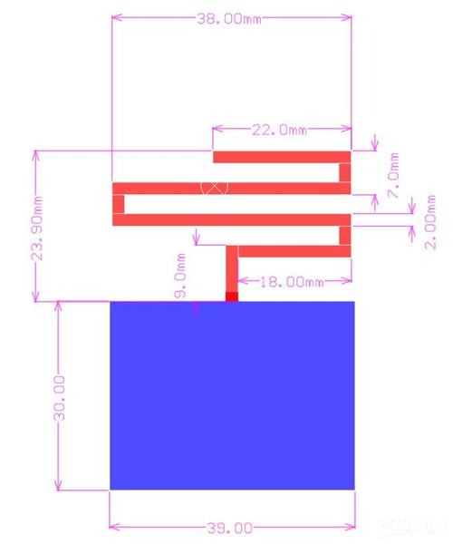
Because there is no ground beneath antenna, the thickness of PCB will not effect the its characteristic. So you can use this antenna for popular thickness pcb, etc 1.6mm, 0.8mm..
For any question, you can make on this post. Thank you very much!


