


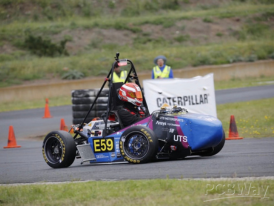
University of Technology Sydney's Electric FSAE Race Car
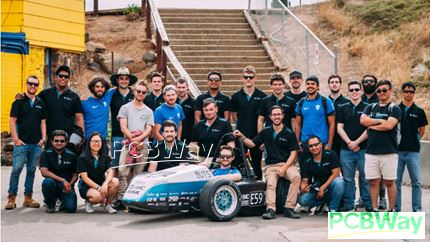
UTS Motorsports, the University of Technology Sydney’s Formula SAE team, is a multidisciplinary student-led project that designs, builds, tests, and races an electric Formula SAE vehicle in the Australasian competition.
Formula SAE is one of the largest tertiary engineering competitions in the world, bringing together universities from across the globe to compete in the design, manufacturing, performance, and business presentation of a formula-style race car. The competition acts as a proving ground for innovation, not only in motorsport, but also in advanced manufacturing, electric vehicle technology, sustainability, and student-led engineering.
Our project was created to give students the opportunity to apply what they learn at university to a real, high-performance engineering challenge. Instead of only learning theory in the classroom, our team works through the full process of designing, manufacturing, assembling, testing, and presenting a competitive electric race vehicle. This allows students from engineering, business, design, marketing, sponsorships, and communications to gain real industry experience while contributing to a shared team goal.
Our car works through the integration of both mechanical and electrical systems. The vehicle is divided into several key subsystems:
- Electrical
- High Voltage Systems
- Low Voltage Systems
- Mechanical
- Chassis Structures
- Vehicle Dynamics
- Powertrain
- Aerodynamics
- Cooling
Each subsystem plays a crucial role in the performance, reliability, and safety of the vehicle. The chassis provides the structure of the car, the suspension and vehicle dynamics systems control handling, the aerodynamics package improves grip and performance, the cooling system manages heat, and the electrical systems power and control the electric drivetrain.
UTS Motorsports also has a dedicated business team, made up of Marketing, Sponsorships, and Creatives. This side of the team supports the project by growing our presence, managing partnerships, producing content, securing sponsorships, and ensuring the team can continue developing better designs, better production processes, and stronger competition results.
In our latest competition, we completed every event and placed 10th out of 21 electric vehicle teams, achieving our best result since 2019. Building on this success, we are continuing to develop more complex technical systems and improve our manufacturing, design, and testing processes for future competitions.
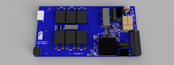
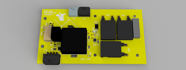
Here are some examples of our projects that use a PCB.
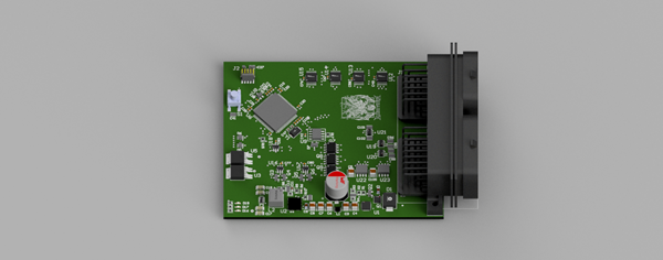
Vehicle Control Unit (VCU): Acts as the main controller for the vehicle, using an STM32 microcontroller to manage the vehicle state machine, process driver inputs, and coordinate communication between key subsystems over CAN. The board interfaces with sensors, switches, and external control modules to determine the vehicle’s operating state and safely deliver torque commands to the inverter during operation.
Brake System Plausibility Device (BSPD): Uses analog signal conditioning, voltage-window comparators, timing logic, and a relay output stage to monitor brake pressure and tractive system current. If heavy braking and high motor current occur simultaneously for longer than the required delay period, the BSPD opens the shutdown circuit to safely disable the vehicle.
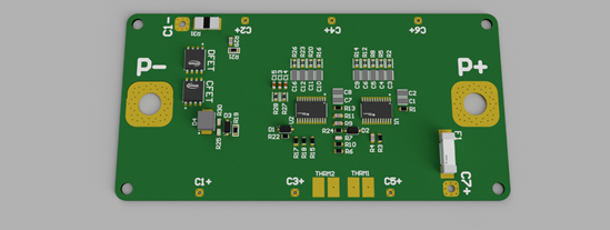
Grounded Low Voltage Battery BMS: Protects the vehicle’s low-voltage battery by monitoring individual cell voltages, pack current, and temperature inputs. The board uses dedicated battery protection ICs with charge and discharge MOSFET control to disconnect the battery during unsafe conditions such as over-voltage, under-voltage, over-current, short-circuit, or excessive temperature. This provides hardware-level protection for the grounded low-voltage system, which powers the vehicle’s control electronics and safety systems.
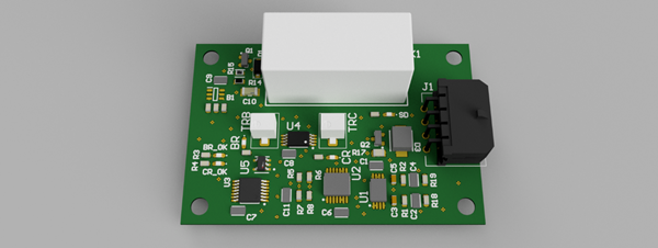
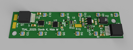
Tractive System Active Light (TSAL): Uses control logic and dedicated LED drivers to indicate the status of the vehicle’s tractive system. The board drives red and green LED strings from the GLV supply, providing a clear visual indication of whether the high-voltage system is active or inactive.
Precharge Board: Controls the precharge process for the tractive system by temporarily bypassing the positive contactor through a resistor network, allowing the inverter DC-link capacitor to charge in a controlled manner before the main contactor closes. The board also monitors fault signals from the BMS, IMD, and PDOC, and opens the shutdown circuit if any of these systems report a fault.
Discharge Board: Discharges the inverter DC-link capacitor after the tractive system is shut down, allowing stored high-voltage energy to be safely removed. The board is located after the MSD so that the DC-link can still be discharged if the MSD is operated, and uses an isolated DC-DC converter and discharge resistor network to provide controlled discharge functionality while maintaining separation between the GLV and tractive system domains.
- Comments(0)
- Likes(0)
 More by UTS Motorsports
-
 An international student based competition to design, manufacture and test an open wheel formula sty
Competition Introduction with related photos:The competition is Formula SAE (Society of Automotive...
An international student based competition to design, manufacture and test an open wheel formula sty
Competition Introduction with related photos:The competition is Formula SAE (Society of Automotive...
-
 University of Technology Sydney's Electric FSAE Race Car
UTS Motorsports, the University of Technology Sydney’s Formula SAE team, is a multidisciplinary stud...
University of Technology Sydney's Electric FSAE Race Car
UTS Motorsports, the University of Technology Sydney’s Formula SAE team, is a multidisciplinary stud...
-
 UTS Motorsports FSAE Electric Race Car
UTS Motorsports, the University of Technology Sydney’s Formula SAE team, is a multidisciplinary stud...
UTS Motorsports FSAE Electric Race Car
UTS Motorsports, the University of Technology Sydney’s Formula SAE team, is a multidisciplinary stud...


