Sheffield Formula Racing: Going Electric
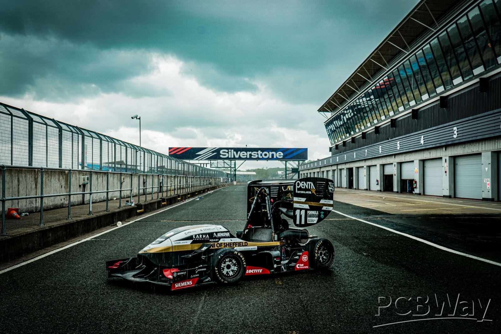
Sheffield Formula Racing are a team of over 70 engineers, designing, building and racing a single seat, F1 style, racing car. We are currently in our 15th year and have had major success in the past, with Sheffield winning the FSUK competition in 2021, and more recently, we have entered the lightest car on-track for 3 years in a row.
This year marks a major milestone for the team, as we are switching from an Internal Combustion engine to an electric powertrain. This will make for a busy year for the electronics subteam. We are building a whole new high voltage system including a battery, BMS, accumulator, ECU and more. Because of this, PCBs are scattered throughout the car. Let's take a quick look at what some of our PCBs do:
BSPD Braking System Plausibility Device
This device takes input from the brake pedal and the accelerator pedal. If any problems are detected like the brake pedal being pushed further than it should be able to be or both the accelerator and the brakes being pressed together for a long time, the system will shut the car down. The actual brakes are purely mechanical with this device being a safety feature.
Steering wheel
Our steering wheel has quite a complicated PCB in it that not just takes input from the various buttons and paddle but also outputs data on status lights and a display. It communicates over the CAN bus as most of our PCBs do but through a connector embedded in the steering wheel attachment mechanism. This makes the steering wheel easy to remove for the driver to exit the car quickly.
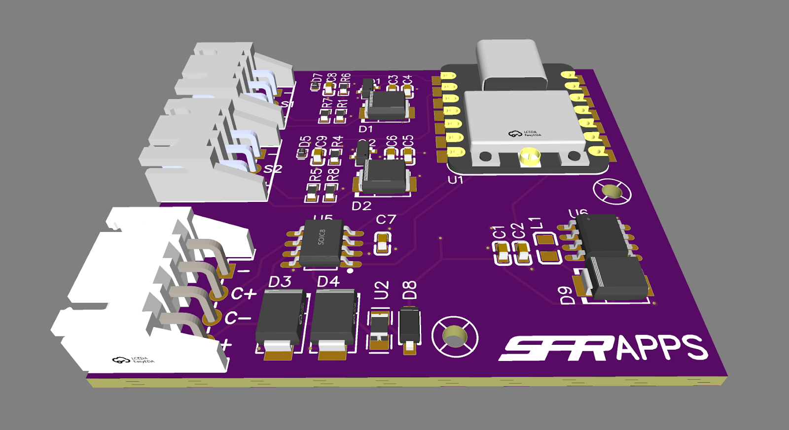
APPS Accelerator Pedal Position Sensor
This is a key component of the car, it reads the location of the accelerator pedal and is a key component of the safety systems of the car. As you can imagine, if it were to be badly designed, it could either stop the car from going anywhere or accelerate the wheels indefinitely. Therefore, 2 sensors are used to read the pedal and many safety features have been implemented.
I designed the circuits and PCB for the APPS. You can see, it is quite a simple device based on an ESP32 microcontroller. It takes 2 analogue inputs from 2 separate potentiometers on the accelerator pedal, providing redundancy and filters the inputs than puts them through the ADC. The microcontroller processes these values and all being well, sends them to the ECU over the CAN bus which ultimately controls the motor speeds.
There are 3 DC to DC converters on the PCB, lowering the voltage from 12V to 5V. One powers the MCU and is a switching converter making it more efficient. The others are low drop out converters that power the sensor circuits, providing redundancy. With the load on these regulators being so low, switching regulators may be unstable.
Arguably the most important piece of circuit design on the board is the ADC filtering circuits.
They first use a 100K pull down resistor. This is an essential safety feature as if not included, the sensors could be floating (Showing random voltages from electrical interference) when disconnected. Next, a 4k7 and 9k1 resistor pair act as a potential divider, taking the maximum voltage on the input from 5V to 3.3V that the ESP32can manage. Then, there is a 1nF capacitor that takes any high frequency noise out of the input and finally, a TVS diode with clamping voltage of 3.5V protects the analogue input from over voltage (12v shorts are surprisingly likely to happen in the car).
With the support of PCBWay, we would be able to produce high quality PCB’s and ensure our first electric powertrain is both powerful and reliable. We are extremely excited about the possibility of collaborating with PCBWay and look forward to their support over the coming year.
- Comments(0)
- Likes(0)