Servo Electronic Speed Controller
Introduction
The problem with normal servos is that there isn't too much you can do with them. There is one wire with the servo and it is used to communicate the position of the servo with a pwm signal. The problem with this is that you cannot control the torque / velocity of the motor, which means that compliancy in servos is impossible. You also cannot communicate with what is actually happening on the board back to to microcontroller back, so that's another issue.
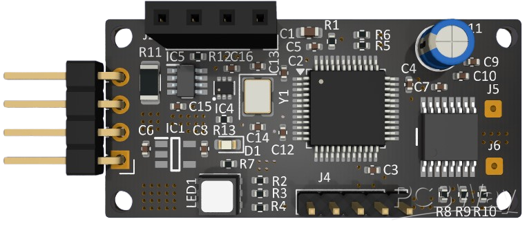
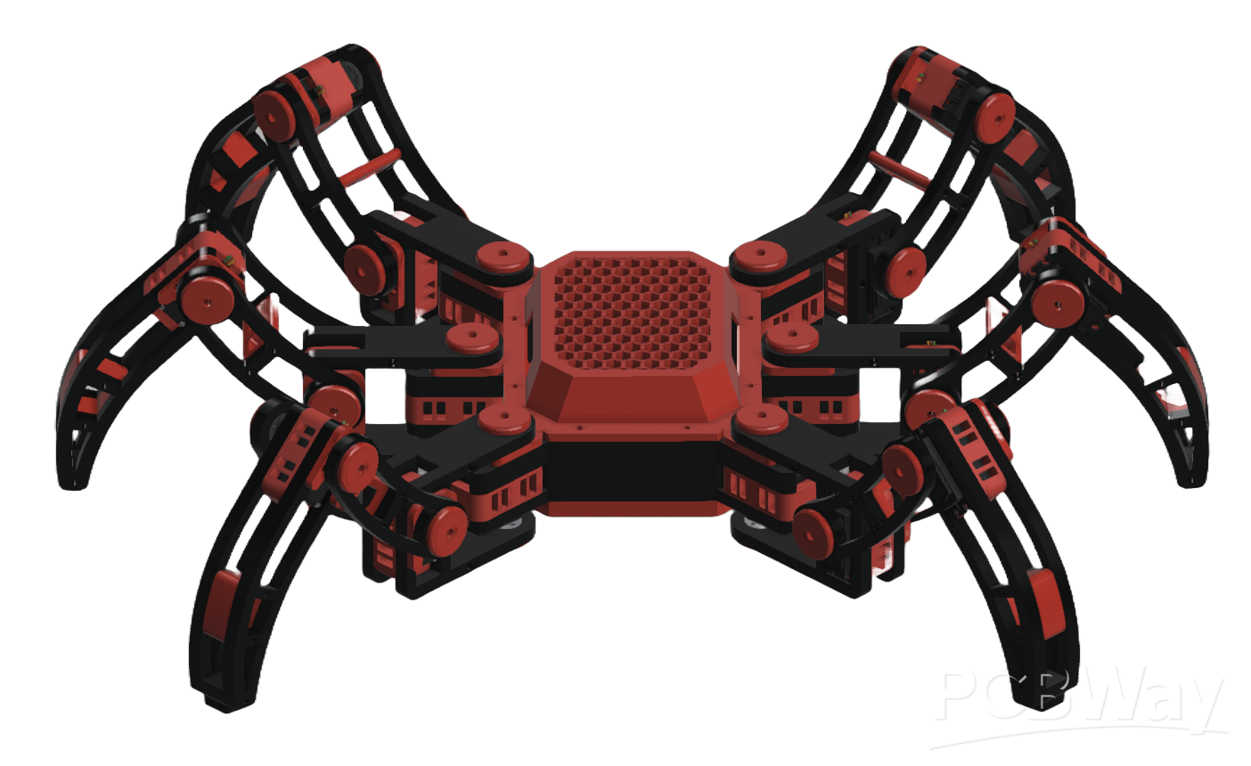
With this board, I planned to not only be able to control a servo motor's torque, position, and velocity using feedback from a better encoder, I also planned to be able to read and communicate back the current, temperature, position, and other variables back to a select microcontroller. This is for a bigger project, where I plan to connect all these servos to a hexapod robot, which the image could be found below.
Features
Power Regulation
The board uses a AP2112K to have a stable supply of 3.3V at 600mA. This gives all the sensors and microcontroller its needed voltage while also allowing the motor driver to use the normal servo voltage (usually around 7.4V).
Current and Temperature Recording
The board uses a INA236 (Current, Voltage, and Power Sensor) and a TMP102 (Temperature Sensor) to get the power consumption and temperature of the board. They then communicate back to the microcontroller (STM32F301C8T6) through the same I2C bus.
Position Recording
The board has outward connectors to a MT6816 to record the position of the board. I plan to create an enclosure for the encoder, which uses SPI communication to go back and forth with the board.
Motor Control
The board uses a DRV8876 to control the boards position, velocity, and torque. It has a current-sense for the motor, which will help in figuring out the current / torque ratio while also allowing me direct control using a DAC for the current limiter instead of a voltage divider circuit.
Outward Communication
The board has outward UART pins and SWD pins. The UART is to connect to the main board / microcontroller, while the Serial Wire Debug is used to program the board.
Analog Inputs / Outputs
I selected this board (STM32F301C8T6) mainly because it was the smallest board with full analog compatibility. I mainly need it for the motor driver since I need a analog input to see the current current and a analog output to regulate the current.
Apply for sponsorship >>- Comments(0)
- Likes(3)