Revolve Racing F1 in Schools Car
Our Approach
This is our introduction section to be handed in as part of our engineering portfolio which contributes to the points earned in the competition. It outlines what design approached we intend to use. More, complete documentation will follow once our car develops further.
In a way, the design objectives for F1 In Schools might be the easiest of any engineering competition to set out. The car doesn’t have to turn; it’s downforce isn’t measured, and wings are purely for aesthetic purposes. The only criteria for what would make a winning car was its speed. Before starting on the design, we set out the variables at play: what couldn’t we, (and more importantly), what could we control.
F1 in schools provides the cartridges - compressed CO2 that is pressurised under the jurisdiction of the factory, not us, so changing the pressure, size, or impulse of the cartridge was not possible. As a design team we briefly played with the thought of adding a nozzle, (which is known to increase impulse by 10-20%), but after consulting the regulations we realised this could not be done legally. [FIGURE 1]. It was safe to put the power system into the category of variables which we would not be able to control, and we would simply have to design around them.
With the thrust locked, the equation for the car could be resolved down to its simplest terms. Net force forward equals thrust minus drag; and drag we very much could control.
The Critical Equation
Drag = Coefficient x Density of Fluid x Velocity2 x Reference area.
Breaking down the equation helps make it easier to understand. Some of these factors are easy, fixed variables. The, “Density of Fluid,” is in our case air, about 1.225 kg/m3 at sea level. Velocity likewise is just a reference to the speed of the car. What’s interesting is that drag scales with the square of velocity - the faster the car goes the harder we’ll have to push through the air to keep accelerating. Velocity is a maximum target though, not a minimum one, so we’ll simply have to design better to overcome the challenges. This leaves the drag coefficient, and the reference area. Starting with the latter, this, (in its most simplified form), basically means the front cross-sectional area of the car. It was surprising to me when looking at the cars designed in previous years that fewer people chose to follow the same approach as us in terms of making the frontal area as small as possible. The only explanation that seemed obvious to me was a difference in the rules concerning spacing in front of and behind the wheels, which have become significantly harsher recently. In previous generations of cars, it made sense to divert airflow over the wheels as cleanly as possible, building an almost unibody shell with the wheels as part of the outer body. This year though, due to keep out zones, this won’t be a possibility for us.
Inertia
Drag isn’t the only thing to consider though. Inertia will play a huge role in how fast our car can accelerate to maximum speed thanks to the equation
F = ma
Here, m refers to mass and a acceleration. Out CO2 canister will produce a set amount force – or, “impulse,” and acceleration will scale directly proportionally with mass. Simply put, the lighter our car is the more it will accelerate during the time when the gas is firing.
Our wheels will also have inertia though, which will have a huge effect in determining the top speed we can reach. Some simple maths demonstrates just how important the inertia of our wheels will be.
Assuming a top speed of ~100km/h or ~27.8m/s
Wheel diameters are permitted to be between 28 and 32mm
Giving a circumference of 87mm, or 0.087m
Meaning that at top speed the wheels will speed at ~320rps, .
We must then extract the inertia of a wheel. For the sake of demonstration, let’s look at both the inertia of a solid wheel of diameter 28mm and length 17mm, which are the minimum dimensions for the rear wheel of an F1 in schools car. We’ll use PLA plastic as a not unreasonable material for the wheel of an aggressively weight saving car, while maintaining manufacturability. PLA has a density of ~0.00125g/mm3. Calculating the inertia of the solid wheel is easy.
Volume = 142 x π x 17 = 10,470mm3
Mass = 10,470 x 0.00125 = 13g
Inertia = (mass x radius2)/2
Inertia = (0.013kg x 0.014m2)/2 = 0.000001274kg.m2
Now we use our value for inertia to work out kinetic energy:
Rads/second = 320rps x 2π = 2,010
Rotational KE = Moment of inertia x angular velocity2 x 0.5
Rotational KE = 0.000001274 x 2,0102 x 0.5 = 2.6J
2.6 Joules certainly isn’t a huge amount – even when multiplied by the four wheels of the car at 10.4 Joules.
But how does it compare to a hollow wheel? We can use much of the same maths as before, but this time the wheel will have an inner diameter of 26mm and 2mm thick walls.
Volume = 10,470 – (132 x π x 17) = 1,440mm3
Mass = 1,440 x 0.00125 = 1.8g
Inertia = (0.0018 x 0.014m2)/2 = 0.0000001764kg.m2
Rotational KE = 0.0000001764 x 2,0102 x 0.5 = 0.36J
That’s a pretty monumental difference in inertia by doing little more than hollowing out the inside of the wheel. It’s little things like this which shaped the design ideology of the car – finding as many places where we could save just a few joules of kinetic energy
______________________________________________________________________________________________________________
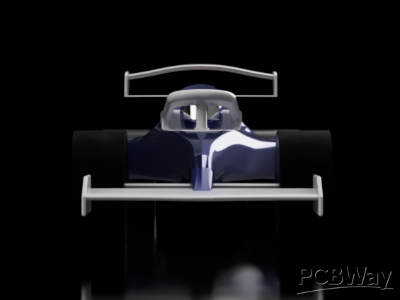
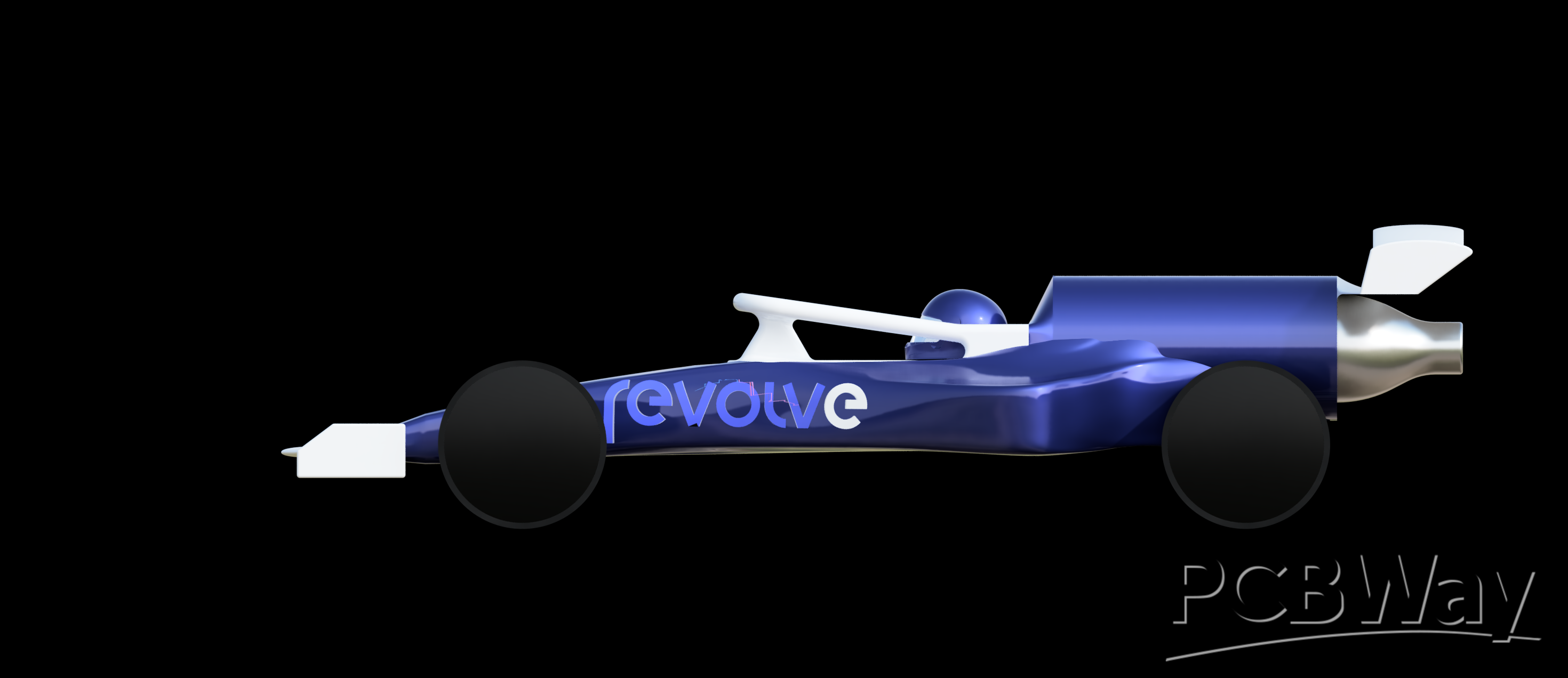
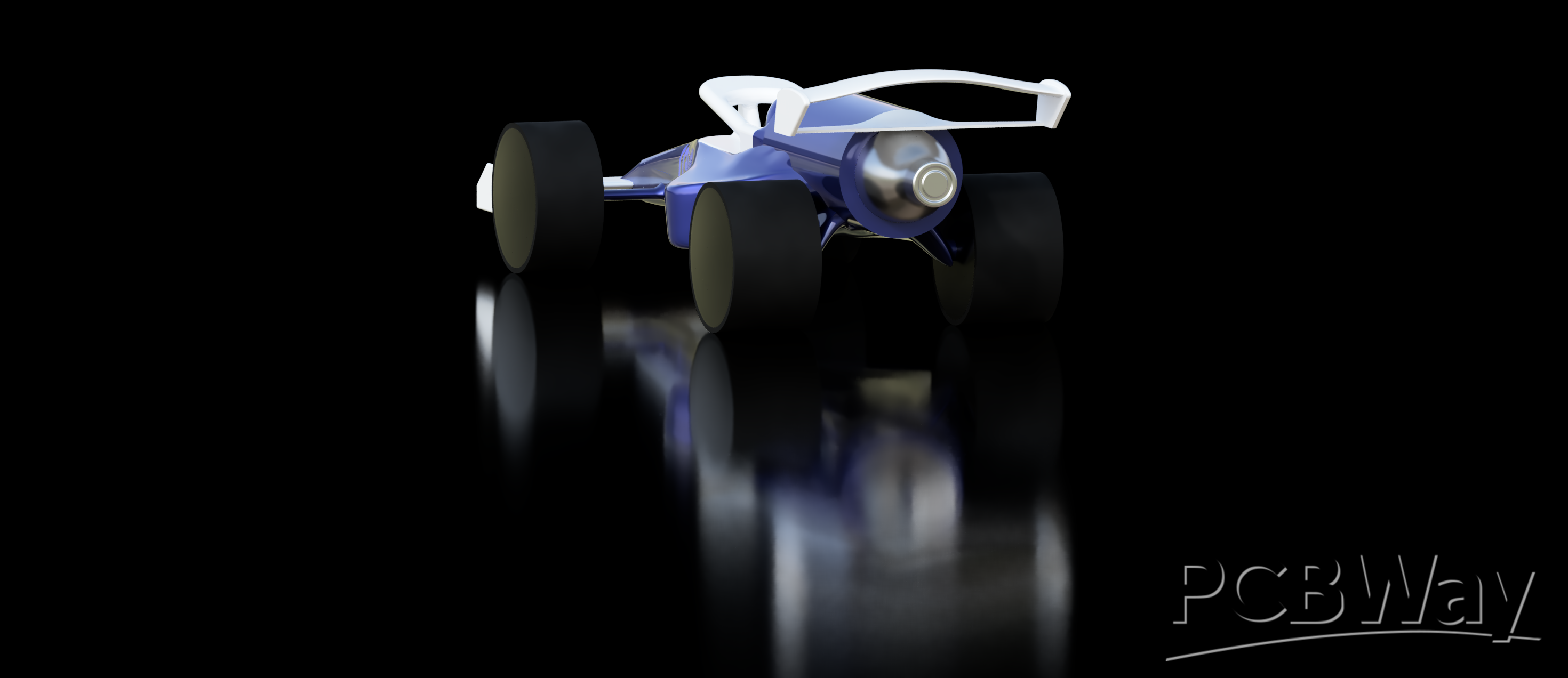
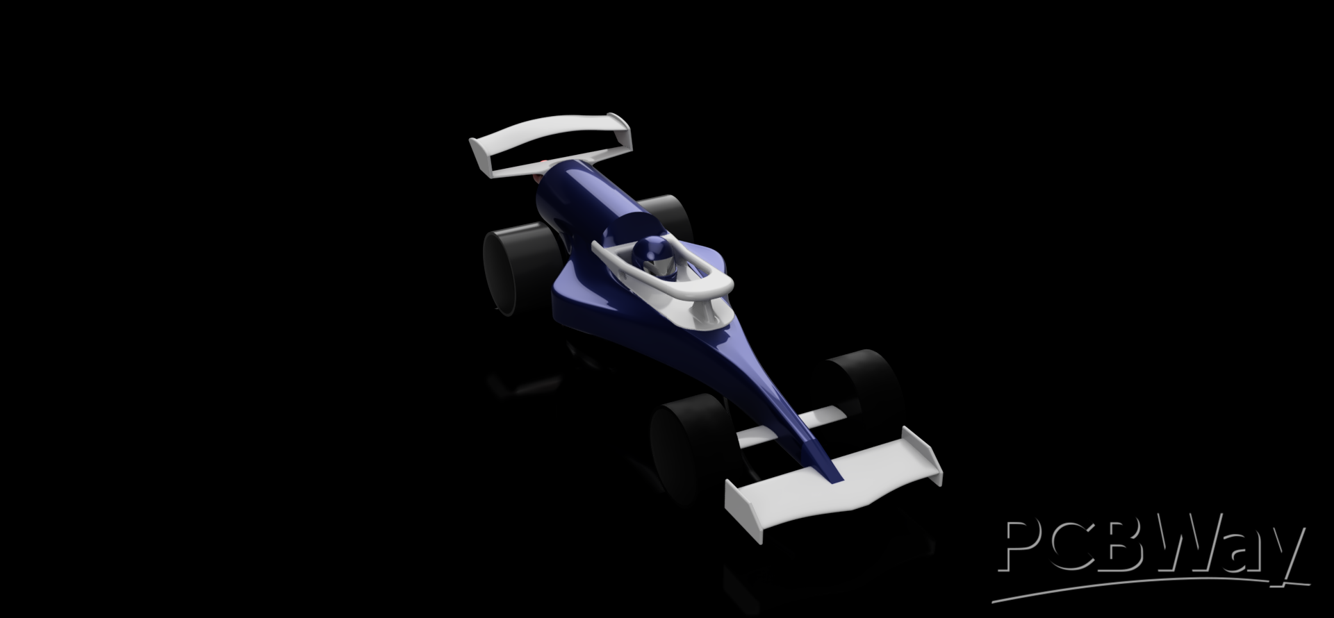
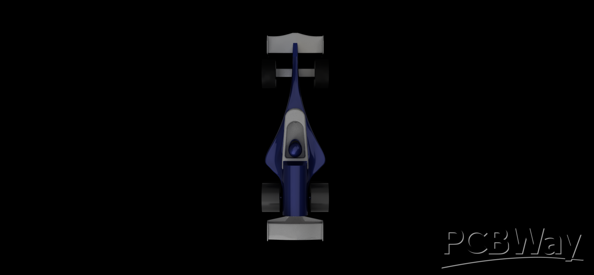
The Car so Far
Below are images of our current car design
- Comments(0)
- Likes(0)