


Promote robotics and artificial intelligence research
Competition Introduction with related photos:
Our team participates the RoboCUP (//www.robocup.org/) and CBR (//www.cbrobotica.org) universitaries competitions, in the Small Size League (//wiki.robocup.org/wiki/Small_Size_League),
Small Size League
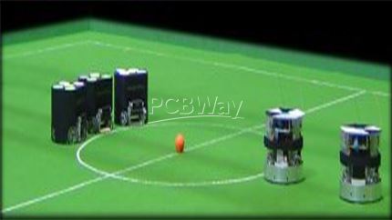
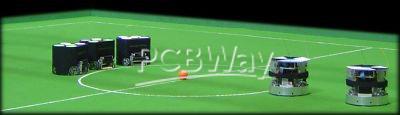
RoboCup is a competition domain designed to advance robotics and AI research through a friendly competition. Small Size robot soccer is one of the RoboCup league divisions. Small Size robot soccer, or F180 as it is otherwise known, focuses on the problem of intelligent multi-agent cooperation and control in a highly dynamic environment with a hybrid centralized/distributed system.
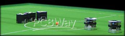 of six robots each. Each robot must conform to the dimensions as specified in the F180 rules: the robot must fit within an 180 mm diameter circle and must be no higher than 15 cm. The robots play soccer with an orange golf ball on a green carpeted field that is 9 m long by 6 m wide.
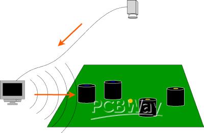
All objects on the field are tracked by a standardized vision system that processes the data provided by two cameras that are attached to a camera bar located 4 m above the playing surface. The vision system - called SSL-Vision - is an open source project maintained by the league’s community.
Off-field computers are used to communicate referee commands and position information to the robots. Typically, these computers also perform most, if not all, of the processing required for coordination and control of the robots. Communications is wireless and typically uses dedicated commercial FM transmitter/receiver units.
Building a successful team requires clever design, implementation and integration of many hardware and software
sub-components into a robustly functioning whole making Small Size robot soccer a very interesting and challenging domain for research and education.
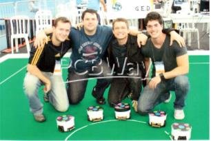
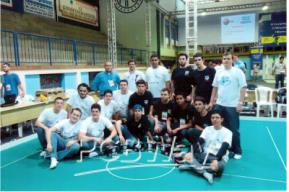
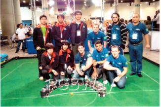
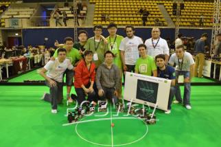
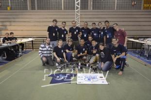
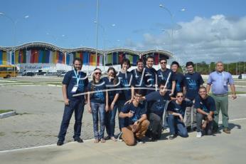
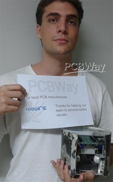
Community Introduction with related Community activity photos:
Our community is a robotics team RoboIME (www.roboime.com.br), that is part of the laboratory of robotics and artificial intelligence of the Militar Institute of technology (www.ime.eb.br), we have already taken part of some competitions like:
LARC 2010
OBR 2011
RoboCUP 2012
RoboCUP 2013
OBR 2014
ROBOCUP 2014
And have already achived some results like:
In 2011 we were vice-champions of Latin American Robotics Competition (LARC).
In 2012 we were the vice-champion na Latin American Robotics Competition (LARC)
In 2014 we were in received the fourth place in Latin American Robotics Competition (LARC)
BENEFITS:
Target market exposure:
Logo in the sponsors area on our team’s site (//www.roboime.com.br/), Logo in the competition banner,
Post in our facebook: https://www.facebook.com/roboime/
Contact with brazilian’s market
Contact to Brasil’s young engineering talents working in the project,
Project Introduction:
Embedded System RoboIME electronics consist of nine boards: (a) the Main board, responsible for communication between the other boards; (b) the Stamp board, responsible for the embedded computations; (c) the Kicker board, responsible for maintaining high voltage and activate the kickers; (d) five motor controller boards which are responsible for the robot’s motion control and the dribbling device. (e)Transceiver board, which is responsible for the link between the robot and the main computer.
Looking forward to participate this year’s LARC competition, we aim to upgrade the project by enhancing the electronic design. We are making the layout of all boards from scratch, starting for the main boar and motor controller board, using a new platform, the altium designer, and paying much more attention to details like the routing dimensions. We are also changing the assembly process that used to be manual, trying to use an automatic pick and place, the NEODEN TM245PA.
Project Details
The Main Board
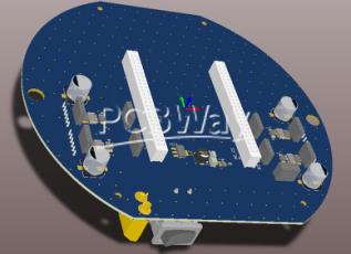
This board features a socket to plug the boards in: the kicker’s sensor, a optical sensor that is used to detect if the robot is with the ball possession, dribbler motor, which makes possible to the robot to spin and to move backward without lose the ball, four wheels’ motors, four quadrature encoders and the power supply with safety devices.
We are making some changes on this board like substituting the former true hole fuses and capacitor for newer smt resettable fuses and smt capacitors, and adding a current sensor the ina220 to have a precise real time feedback of the current that flows in each motor. We are also adding a connector to the NRF24 transceiver and making an experience with a bulk voltage regulator.
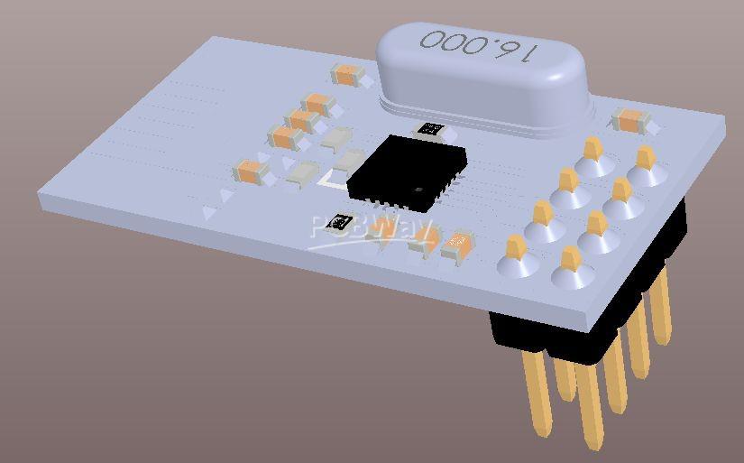
Stamp Board
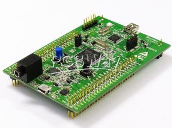
This board is responsible for performing all the logical functions. Serving as a brain of sorts for the electronic system. There is an embedded STM32F407VG micro-controller, with an ARM Cortex M4 as main CPU, 1 MB Flash, 192 KB RAM memory, working at 168 MHz, that was programmed in C language using CoIDE and Eclipse IDEs. The main function of the embedded system is to receive the data from the AI and convert it into movement. So, there is a Proportional Derivative Integrative Control sampling the real wheel’s velocity, comparing with the desired and outputting the appropriate voltage to the motor. That control has the fundamental importance of look for the right wheel’s velocity. There is also a current control that doesn’t permit the Motor Controller Board to burn out.
Kicker Board
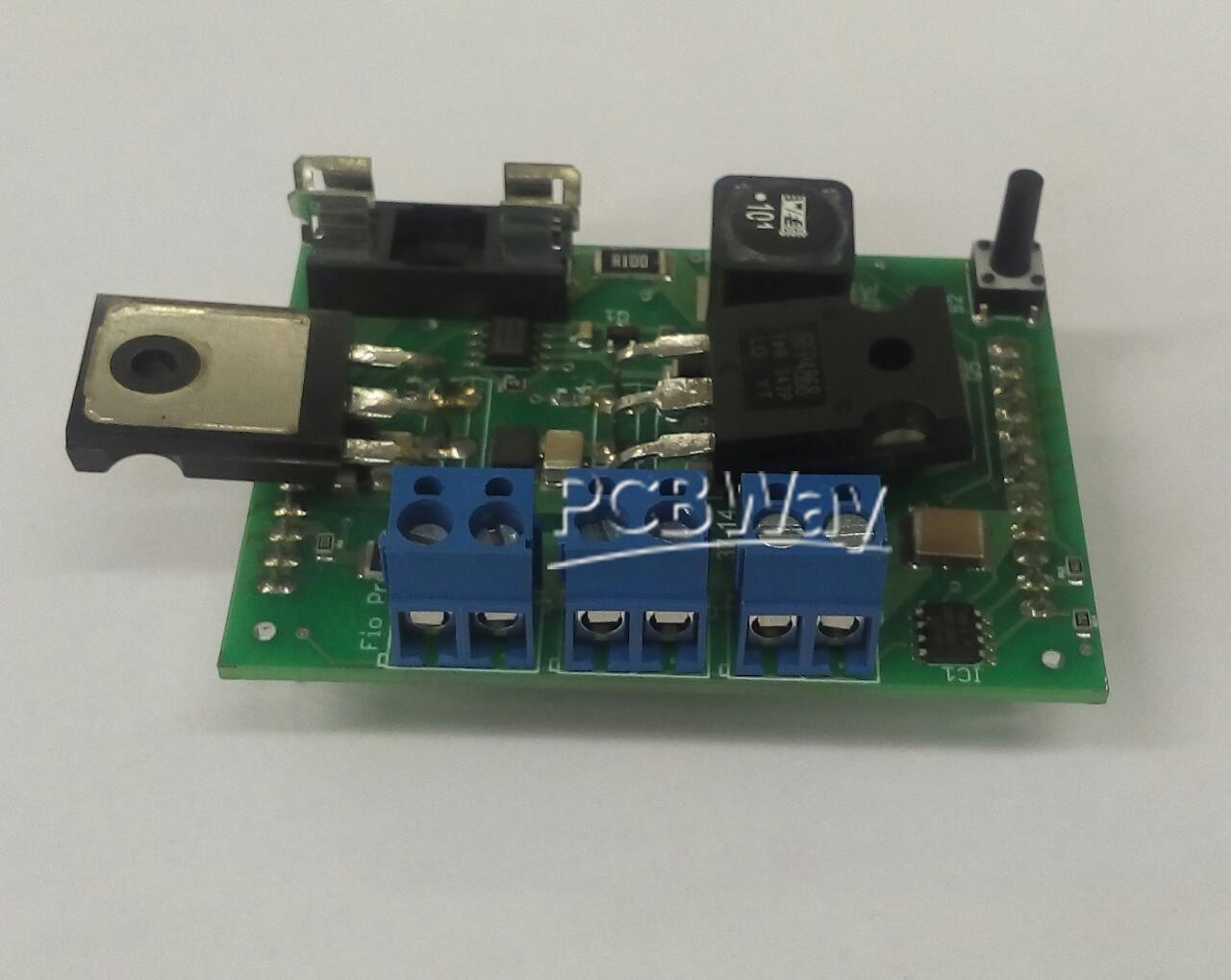
This board is responsible for produce the high voltage used to activate the two coils, controlling the kick strength and discharge almost instantly all the power stored on the coils. There are two kinds of kick, the forward kick and the high kick. There are two steps in this board: charge and discharge. The first has the unique function of keep a constant output of 180V DC from a input of 7 8V DC. A DC-DC step-up power supply controlled by the MC34063 IC and two electrolytic capacitors of 2200 μF, 200 V are used for this task. The second is to drive the kickers. In this part are used one TC4427 Mosfet Driver IC and two IRFP4868PBF Power Mosfet that are responsible for close the high voltage circuit of the first step with the ground through the coil, converting electrical into mechanical energy. A precise control of the actuation time ensure that the kick will occur with the right velocity.
Motor Controller Board:
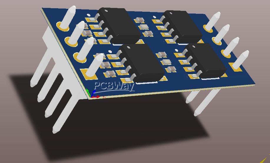
The idea of the RoboIME electronic is to modularize the electronic project. So, there is one controller module board for each wheel motor. If one of them burns out, it is possible to exchange it quickly. Each board has two TC4427 (MOSFET driver) and two IRF7319 (complementary half H bridge). These ICs create an H-bridge, allowing the velocity control in both directions through a Pulse-Width Modulation, converting a digital signal input into an analog output.
Transceiver Board
The transceiver board is responsible for the link between the micro-controller and the main computer through a NRF24L01 transceiver. The first is done using a own protocol, operating in the 2,4 GHz band, the second is accomplished through the Serial Peripheral Interface Bus (SPI), a standard.
- Comments(0)
- Likes(1)


