


Project Valkyrie
Valkyrie, the new electronics system: RICHARD MK III
Our rocket, Valkyrie, is a bi-liquid rocket that uses isopropyl alcohol as fuel and nitrous oxide as oxidizer. Our engine is 3D printed in steel and has coolant channels around the chamber, so the fuel is cooling it down while operating along with optimizing the burn of the fuel. The Valkyrie rocket has an upgraded version of the Dragonfly’s “the Stack” - electronics named “The Rack” - due to the new design involving board placement like that of slot-in RAM in a computer.
The Rack (Electronics)
In our new rocket, Valkyrie, we will use the same flight computer we built for the previous rocket, Dragonfly, but with some upgrades. This flight computer will be put together in a rack, like RAM modules slid into a motherboard supported in each side and locked into place with a locking mechanism, so it does not fall out from vibration during operation of the rocket.
Our rack has the following boards each with specific functionalities;
Template board
All PCBs in the Rack are based on a template design; an STM32g4 microcontroller with power management, external flash, external EEPROM, CAN transceiver, barometer, and IMU. This allows every board to log data, store configuration files, and communicate with the rest of the boards on the CAN bus.


Telemetry board
The telemetry board is responsible for transmitting in real time data, about the rocket, to the ground station. Among this data, there is information about the rocket's speed, attitude and location. For this purpose, the telemetry board comprises a GPS module and three LORA transceivers connected to the on-board antennas. Thereupon, there is also a similar board on ground used to receive and decode the transmitted data. Finally, the temetry board is integrated in The Rack and communicates with the other boards via CAN bus.
Actuator board
The Actuator board controls the different Servo boards located in different places in the rocket. The board sends out PWM signals for controlling the servos, enable signals to turn on power for the servos, and gets feedback from the servo board.
Main board
The Main board acts as a “leader” of the Rack, making decisions on what measurements need to be taken and which actions should be taken. It does this by requesting data from the other boards on the CAN bus, or telling other boards what to do. The Main board also has an RS422 transceiver, which is used for communication with Mission Control while the rocket is still on the launch rail pre-flight.
Pressure board
The Pressure board measures 7 different pressures in the rocket, in both the engine and the rest of the fluid system. It also reads the measurements from the level sensor, which shows how much oxidizer is left in the tank.
Temperature board
The Temperature board measures 8 different temperatures in the rocket.
Power board
The Power board provides power to the Rack on two separate grounds. It houses three switch-mode power supplies; a logic 5V line, a power 5V line, and a power 15V line. It is also responsible for switching on three different cameras in the rocket right before flight. Additionally, the power board measures the battery voltage and current output of all batteries in the rocket, as well as the power consumption of it’s switch-mode power supplies
Backplane
The Backplane is exactly what it sounds like, a backplane for communication between each board in the flight computer. The backplane connects to each board using a slot in connector, similar to the well known PCI-E 4x slot, providing more than enough connection pins for each board. This enables super fast board changes in case of a malfunction, hardware failure etc. Besides handling all communication between flight computer boards, the backplane also connects the flight computer to the rest of the rocket, eliminating the need for multiple connectors on each board.

Servo board

Controls one pair of servos using PWM signals supplied by the Actuator board. It is supplied with 12.5V from a LiPo battery which is converted down to 7.4V for driving the servos and 5V for powering the on board PWM buffer. An enable signal triggering a current toggle allows for quick shutdown in case of failures.
BMS
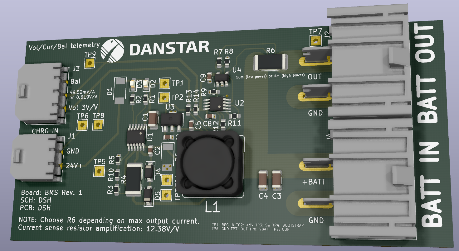
BMS (Battery Management System) is a 2A charging and monitoring board for various 12V LiPo batteries around the rocket, one per battery. Several batteries can charge from a 24V bus.
Ignitor
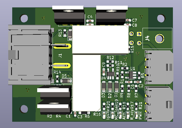
The ignitor board is a crucial part of the rocket, since the ignition of the rocket is controlled on this board.
The board is supplied with a 12.5V LiPo battery and takes in 3 signals for ignition: Rocket_ready, Rocket_ARM and MC_Ignite. All 3 signals have to be set high in order to generate the ignition and are controlled through an AND gate with diodes.
The current generated for ignition is done by a LM1084 which outputs 1.5V and 4A.
2 relays are added for safety features, as a mechanical shut off.
5 LED’s are added for debugging to see if the signals are activated.
Middleman

The name of the middleman board stems from its literal function, being between our COTS (Comercial Off The Shelf) flight computers, and the servos executing the recovery operations. It is a competition requirement that the flight computers that deploy the parachute be commercial, and not made by us.
This introduces a problem, as our parachutes are deployed by servoes, and the flight computers output either a high or low signal, and thus cannot control servos. This is where the middleman comes into play, receiving data from the flight computers, and generating a PWM signal that moves the servos accordingly. Apart from controlling the servos, the board has feedback features to verify whether the servos have actually moved when the signal is sent, and whether the corresponding parachute has deployed. All this is communicated to the central “Rack” flight computer.
Launch rail and keybox board
Two additional PCBs will be designed; a launch rail board and a keybox board. The keybox board sits inside a little box with a keyhole at Mission Control, roughly a kilometer away from where the rocket is to be launched. A key can be inserted in the keybox, and turned to three positions: OFF, ARM, and IGNITE. The keybox also sends RS422 data along a kilometer long cable to the launch rail board, which sits in a launch rail cabinet, which is mounted on the side of the rocket’s launch rail.
Support from PCBWay would be an enormous help towards reaching our goal in time! Our next rocket is scheduled to launch in October 2021 from Portugal and here, we will hopefully break the world record for height reached by a student built bi-liquid rocket!
- Comments(0)
- Likes(0)


