Modular RF Module
In a world of ever growing AI applications with autonomous navigation and machine learning, a modular easy to integrate GNSS and IMU will help not only the WE MARS (WeMars.org) but any team looking to include a high performance module in their design! This project is my first RF Design and it has been through 3 different revisions already. All 3 revisions I learned something regarding the design that was fixed in the next revision and now this board is the optimization phase that will increase the accuracy of the GPS coordinates by by 99%. If you want to hear the story about how this module got to where it is, then grab a nice drink and sit back and read.
Phase 1: THE INAGURAL BRINGUP

The initial design was originally just the GNSS receiver (U-blox NEO-M9N-00B) that was equipped with USB-C's for CANbus (and a CAN Transceiver) and communication and had an ESP-32 Microcontroller on it. This design had several mistakes on it. For starts, 3 different LDO's were used, which was completely unnecessary and they were difficult packages to hand solder leading to increased delays in the assembly, The connectors chosen were also sub-optimal. The SMA antenna connector was the wrong mate for the antenna we purchased and 2 LED's were missing for indication of ESP programmability and satellite connectivity, All of these design mistakes were taken into consideration for the next revision!
Phase 2: THE 2ND PURSUIT
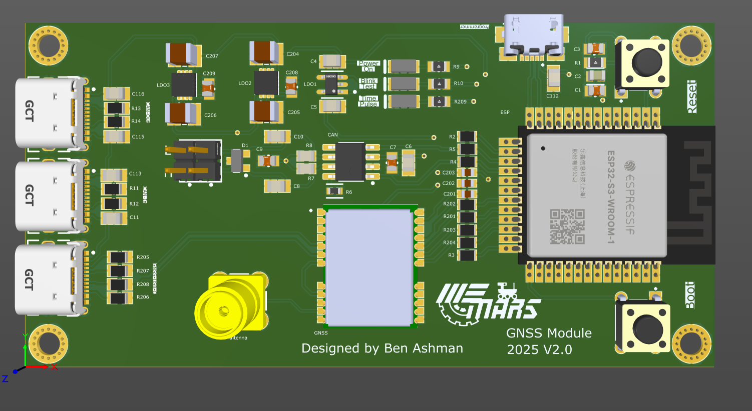
The 2nd revision is noticeably better with the correct antenna header now being used and the status LED's now fully being implemented. However, the 3 LDO's were still used, partly because we already had the chips so we decided to just use what we have I guess (looking back idk why I didn't just change that then and there). I also added series termination resistors to the GNSS data lines and added mounting holes to the PCB to mount it down for when it is added to the rover. However, there were still several mistakes. For starters the decoupling capacitors of the GNSS were placed HORRIBLY. Secondly, we still stuck with USB_C for CANbus and the USB for data to the GNSS, both of which were redundant as we now switched to using RJ10 connectors for CANbus and that's the only way the data is coming from this module. There was a logic mistake with the GNSS data select. I didn't realize that one of the pins needed to be pulled high to enable I2C/UART communication to the ESP32 meaning we could only collect data through SPI, which, wasn't really preferred. Lastly, a bias T was not included in the design which once again made our antenna unusable since it only had 1 wire for data and power which required a bias T on the PCB to get both the RF data and supply the antenna with power.
Revision 3: OH YEAH IT'S ALL COMING TOGETHER NOW
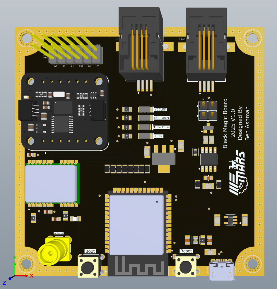
This is our current revision of the GNSS receiver that has been already purchased and currently being soldered/tested to confirm functionality of everything. However this board is a MASSIVE jump from our second revision as this board not only incorporates the GNSS receiver, but also adds an IMU (Adafruit BNO055) to this module making the new module capable of location AND orientation! This module also now FINALLY used only 2 LDOs which were significantly easier to solder and one was used for the ESP32 + IMU and one was used for the GNSS, since, they operated at slightly different voltage levels (3.3 vs 3). The GNSS receiver also had the bias T added and the external pull up resistor so we can use UART and I2C communication from the GNSS. The decoupling capacitors were also placed significantly better and the CANbus connectors were changed to RJ10s used everywhere else on the Mars Rover!
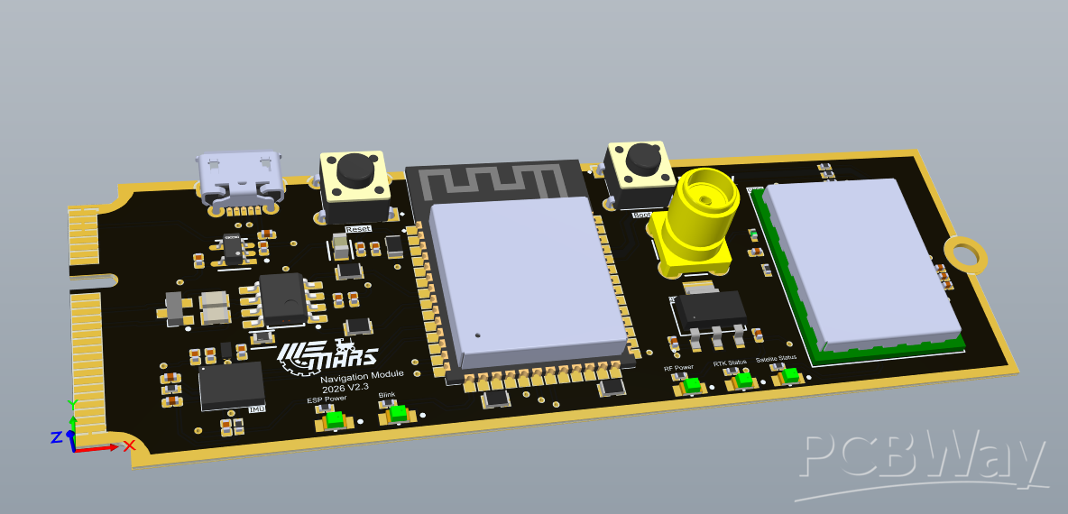
Phase 4: THE FINAL UPBRINGING

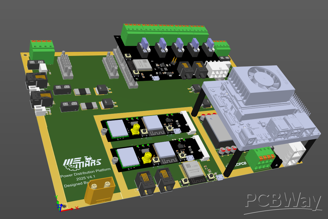
Finally, this brings us to the final revision (hopefully) of this project where we reach the optimization portion. Main changes in this design are the GNSS chip being switched to a ZED-F9P-05B which is capable of Real-Time Kinematic which allows for 2 GNSS receivers to be used in tandem to provide correctional data to the primary one allowing for an accuracy of up to 1cm! The IMU has also been broken down into just the chip itself reducing the cost of the module by $26 in components cost and allowing for more freedom to configure the communication of it. The last big change is there are no RJ10 connectors! however there is still a CANbus transceiver, so how is the CAN data being transferred? THE PCIe SLOT!!!! yes this module is being designed so it can fit into a gen3 PCIe mini expansion card slot meaning this board can be replaced EASILY, it can be moved from board to board painlessly, and it can be mounted to boards securely, wirelessly and be screwed down similar to an NVMe drive ( also looks pretty cool too :P)
For this new board the design team will be taking advantage of PCBways PCB Assembly Process and we plan to order 4 boards if possible. This PCB is a 4-layer stack up with impedance control (as are the rest of the revisions) but this one requires the ENIG finish with gold fingers and we are going to get it in a matte black colour. The real cost killer is the components. Attached is the BOM and outlined cost for 4 boards using PCBway assembly (estimate) so we are hoping at least some of the cost can be covered by PCBway to support our efforts in creating a modular, open-source, GNSS/IMU module for autonomous navigation applications!!!
Thank you for reading, and I hope you enjoyed the story of the little RF design that could :)
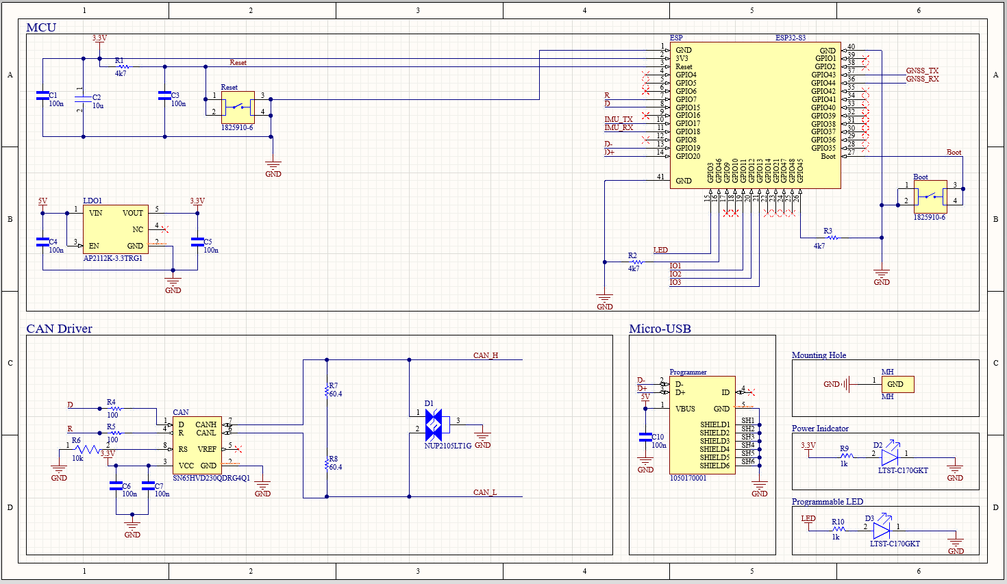
Here are the full schematics:

- Comments(0)
- Likes(1)