


MART Formula Student
WHAT IS MART FORMULA STUDENT?
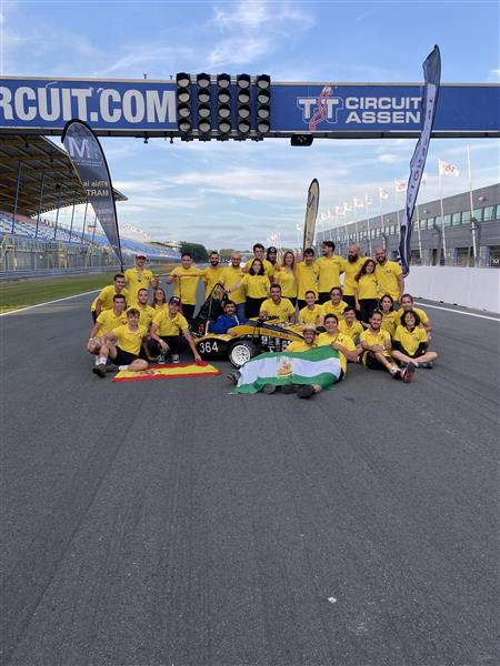
MART Formula Student is a team formed by more than 60 students from 18 different degrees belonging to the University of Malaga who love and share the passion of motorsport. The team is structured in 8 different departments (aerodynamics, chassis, dynamics, electronics, power, suspension, e-powertrain and business) with their respective directors who are responsible for distributing the work of the team. In addition to this, there are the positions of team leader and technical director, who are responsible for organization and management tasks, as well as overseeing technical development respectively. Our main objective this season is the growth of the team nationally and internationally, through competition at the highest level with the new MA23RT, an evolution of the last single-seater with which we obtained very good results such as third place in the acceleration and endurance events in Formula Student Netherlands, or first place in the business event in Formula Student Spain as well as third and fourth place in the acceleration and endurance events of that championship. In addition, this year we have started with the development and production of our first electric car, thus betting on an electric future, with a smaller carbon footprint and more environmentally sustainable. You can find out more about us at:
www.mart.uma.es/
https://www.linkedin.com/company/martfs
www.instagram.com/mart__fs/
In addition, we have a dossier in which we show the activity we have been carrying out:
https://drive.google.com/file/d/1kgcGtVvf3U05aSjxEqIyNTZROpjlZf8F/view? usp=share_link
WHAT THE COMPETITION IS?
Formula Student is a student engineering competition held annually all over the world. Student teams from around the world design, build, test, and race a small-scale formula-style racing car. The cars are judged on static events which are engineering design, cost & manufacturing, business presentation, lap time simulation and technical inspection (safety, chassis, noise, tilt and brake) in addition to dynamic events like skidpad, autocross, acceleration and endurance. It is run by the Institution of Mechanical Engineers and uses the same rules as the original Formula SAE with supplementary regulations.
This is a competition that encompasses many disciplines and you can come out of it very well trained for the world of work. This competition allows you to develop different practical skills to the ones you are taught at university. First of all, we learn to manage and cooperate between different departments, focusing on a common goal, with different meetings and talks between us as well as with sponsors and the different companies we are targeting. In addition, a great deal of resources and time management is necessary in order to meet the objectives on schedule. From the technical point of view, engineers learn to design, manufacture and produce components or software for a real project with limited resources, thus assessing the different options to try to achieve the highest performance at the lowest cost. In this way, thanks to Formula Student, the engineers who participate in this competition gain more experience in a work format very similar to that used by many companies in the workplace.
PROJECT DESCRIPTION
BSPD (Brake System Plausibility Device):
The BSPD is responsible for shutting down the Shutdown Circuit (Ignition and fuel pump) if the "Condition" described below is met.
Characteristics:
- Circuit: Single and NOT Programmable.
- Condition: "Hard" Brake & Throttle (>25%) for a threshold less than or equal to 500 ms.
- Brake Sensor: A pressure sensor shall be used, whose trigger threshold must be less than or equal to 30 bar and that the wheels have not yet locked.
- Connections: All sensors shall be capable of being disconnected for inspections.
- Power supply: Power is supplied to the circuit directly from the Low Voltage Management System (LVMS).
- Reset condition: If the trip condition is overridden within 10 seconds, the BSPD can be automatically reset without power cycling.
Circuit operation:
-Initialization:
When the PowerCycling system is initialized, it produces a signal (delayed ~2 ms) which Initialises the state to "1" of the system.
-Condition:
Both sensors (pressure and brake) are measured and compared to a reference voltage to detect condition trigger thresholds. The triggering of both signals starts the timer (approx. 500 ms), after which a new comparison is made. This determines whether the "Condition" has remained active during this time. If so, a "0" value status is generated and the relay and shutdown are switched off.
-Error:
In the event of a disconnection error, short circuit or overvoltage, the Shutdown Circuit is switched off immediately. This in turn prevents the possibility of an autoreset.
-Autoreset:
If the "Condition" is triggered and therefore the Shutdown Circuit is disconnected, if the condition does not continue after 10 seconds after the event. The system can be reset automatically. This situation is only possible if no error has occurred in the system.
Components needed:
- 16 × 100nF Capacitor
- 3 × 10uF Capacitor Electrolitic
- 2 × 330nF Capacitor
- 1 × 220uF Capacitor Electrolitic
- 2 × Led
- 14 × Diode Zener_2.2v
- 5 × Diode
- 1 × Polyfuse
- 2 × Molex_Nano-Fit_105313-xx02_1x02
- 2 × Molex_Nano-Fit_105313-xx03_1x03
- 1 × Rele 12VDC 5A Pan
- 1 × NPN Transistor
- 36 × 150kOmh Resistor
- 1 × 0.5 Omh Resistor
- 1 × 560 Omh Resistor
- 2 × 2.2 KOmh Resistor
- 4 × 0 Omh Resistor
- 2 × 20 KOmh Resistor
- 2 × 10 MOmh Resistor
- 1 × 1.8 KOmh Resistor
- 2 × 47 KOmh Resistor
- 1 × 5v Regulator LM7805
- 2 × LM324 OpAmp
- 2 × CD4071 OR x4
- 1 × CD4081 AND x4
- 1 × CD4081 NOT x6
- 1 × CD4081 FF-D x2
- 2 × LM555
- 5 × Potentiometer 47KOmh
- 1 × Potentiometer 47KOmh (Screw)
Manufacturing
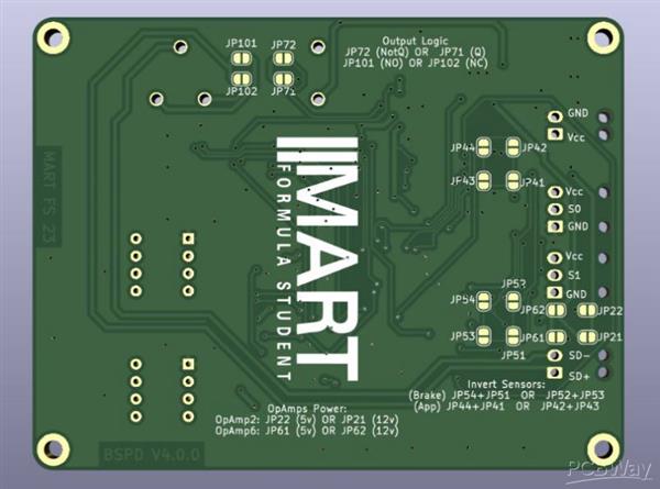
SMD components have been used to manufacture the device. The use of a stencil is recommended for the application of the solder paste. However, this can also be done by hand. The placement of the components can be done either by Pick&Place or manually. Soldering should be done by hot air or by using a convection oven.
Configuration
For correct operation of the BSPD, the following parameters must be set:
1) Reference Voltage of the sensors VApp1 and VBrk1 (depending on their trip threshold).
2) Reference voltages of the error signals: 0.5v, 4.5v and a reference voltage for VC1 (depending on the power consumption of the sensors), the latter to be set experimentally.
3) Sensor mapping inversion
Both sensors are designed to deliver a voltage between 0.5v and 4.5v, but they can map the signal inversely. So in case of sensor comparison, below a threshold. The jumpers JP41 -->JP43 , JP42-->JP44 for the first sensor, and JP51 -->JP53 , JP52-->JP54 must be inverted.
4) Selection of the supply voltage for the comparators.
The comparator operational amplifiers may be powered at either 5 V or 12 V. The selection is made by means of jumpers JP21, JP22, JP61 and JP62.
5) Timer settings:
Timer1 (450 ms)
Timer2 (9500 ms)
The following pins are arranged:
S1 (Start Condition)
S2 (End Timer1)
S3 (End Timer2)
These can be measured using a digital oscilloscope, or alternatively using a microcontroller.

WORDS TO PCBWay
We are aware of the high quality that PCBWay offers, both in its printed boards and in its services, providing fast delivery at very competitive prices. That is why we would be delighted to be able to collaborate with this great company in order to be able to continue fulfilling our objectives, thus forming us as better students.

- Comments(0)
- Likes(12)


