


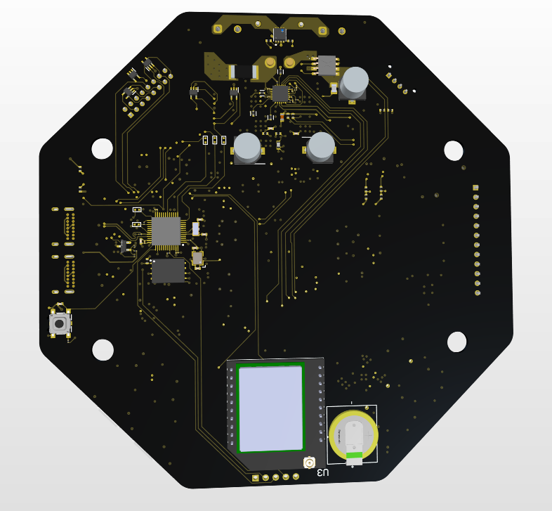
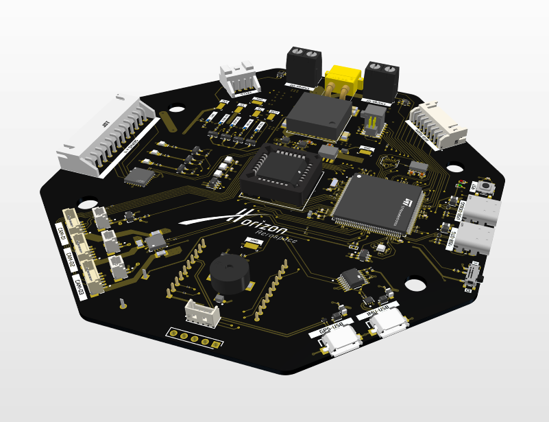
Horizon Aerospace Flight Computer
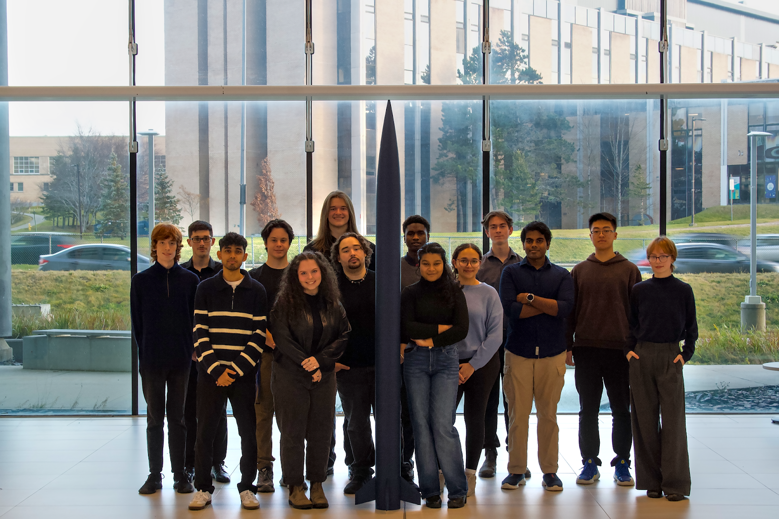
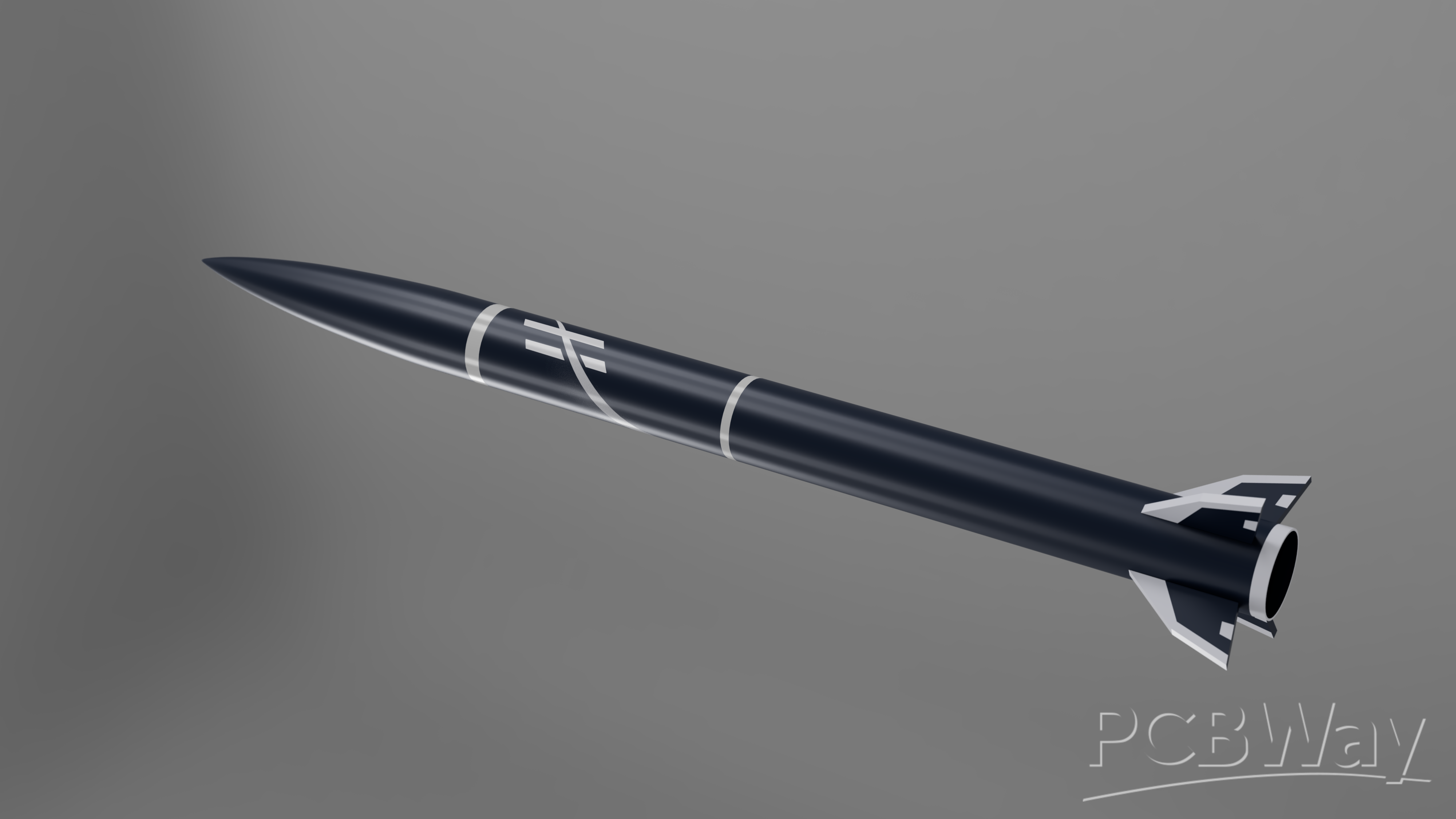
Horizon Aerospace is the first rocket design team at Memorial University of Newfoundland and the only amateur rocketry club in the province of Newfoundland and Labrador, Canada. We are building a Class FAA 2 high power rocket predicted to reach an altitude of of 3000m. Our payload is a set of camera systems capturing the zenith, nadir and horizon views of flight. We will be implementing roll control by utilizing movable tabs on the fins to prevent the rocket from rolling about its primary axis.
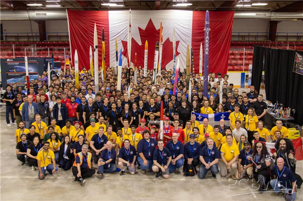
We are planning to participate in the Launch Canada Challenge for the first time, with the goal of designing, building, and safely recovering a Class FAA 2 high-power rocket that meets the competition’s apogee and recovery requirements. This competition will serve as a structured milestone for our engineering process, driving our team to complete full-cycle design, testing, and flight-readiness validation while demonstrating our avionics, telemetry, and recovery capabilities in a national-level launch environment.
The flight computer aboard the rocket is the brain of the rocket which will be in-charge of all stages of flights from launch to recovery. Our flight computer features an STM32H7 microcontroller and numerous sensors that allow in-flight monitoring from the ground station and key activities like performing roll control and handling ejection charges for the deployment of parachutes.
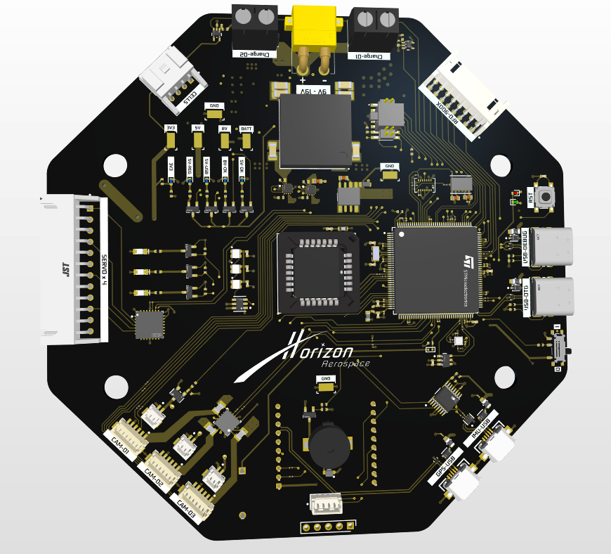
Features of the Horizon Flight Computer
Implementation of Roll Control
The control algorithm for roll control will run on the STM32 chip which will use readings from the inertial measurement unit (IMU) to assess the orientation of the rocket and will send commands to the servos attached to the fins via JST connectors to counteract any changes in the roll axis of the rocket.
Handling of Ejection Charges
The flight computer PCB will be programmed to monitor all stages of flight and will deploy ejection charges for the deployment of the drogue chute followed by the deployment of the main parachute to ensure safe landing of the rocket. The firing of the ejection charges is controlled by the ignition switch on the PCB which features a cascaded MOSFET and op-amp circuit.
Telemetry and Communications
Radio module on the PCB sends and receives signals from a radio module in the ground station. Telemetry data such as readings from the GPS, IMU, altimeter, pressure and temperature sensors will be downlinked during flight for real-time monitoring of the rocket’s trajectory and for recovery once the rocket has safely landed.
Power Regulation
The PCB features a battery monitoring circuitry and buck converters that allow the supply voltage to be converted to 8V, 5V and 3.3V to be supplied to the different components with different voltage and current requirements.
Flight Footage
DJI camera connectors on the PCB provide power and control interfaces for the DJI O4 cameras, allowing the flight computer to command recording throughout the flight. The footage is stored locally on the camera and will be retrieved from the camera after recovery of the rocket.
PCBWay’s support would directly enable us to iterate faster on our avionics and recovery systems, validate our designs through multiple prototype spins, and ensure we arrive at Launch Canada 2026 with flight-ready hardware. We would greatly appreciate your sponsorship support and look forward to building a long-term partnership with PCBWay as our team grows.
- Comments(0)
- Likes(1)


