Hexagonal Modular Robots
Team Bio
We are a team of highschoolers. Although that may make us sound inexperienced, it means we are the most open to learning. Both of us have experience in robotics and know how hard the designing, wiring, and coding of them are, and we are super, super passionate about making a change to make robotics easier for everyone.
Pranay Bokde
I'm a 10th grader at Santa Clara High School, with relevant experience in robotics and engineering. I'm part of a First Tech Challenge Team which went to the international level, and have competed for the past 2 years in science fairs with machine learning and drone projects, reaching the state level both times.
Neel Gowda
I am an avid engineer in 10th grade at Santa Clara High School. My hobbies include robotics, water polo, and badminton.
About This Project
Currently, robots are hard, complex, and require many people to design. This means in areas like search and rescue, where rescue teams might need robots to search ruins or fallen buildings to quickly find people, or in space, where an astronaut might quickly need a tool while floating in darkness, robots are almost inaccessible. We are testing whether modular robotics are a more versatile, stronger, faster, and more enduring approach to design and deploy robots in these environments.
Context
Industrial modern robotics is founded on flexibility and adaptability.
Many applications, such as research, disaster response, and monitoring, require diverse and sometimes rather unusual needs. Traditional robotic systems are rigid, expensive, and require specialized knowledge to build and deploy.
Recent advances in embedded systems, wireless communication, and software simulation have made it feasible to integrate modular systems with powerful software and ease of use. We have the technology to allow people to create robots without touching a single line of code, wire, or design program.
Significance
Multiple systems like the HEXEL system have been designed around this idea, but they don't implement smart control or a software pipeline at all. We expect to find that by designing a new system with our space and power efficient muscles, we can generate modules that are stronger, versatile, and can endure more than previous systems.
Modular robotics is a field well worth exploring, as has been done by projects like HEXEL. We would like to extend this research into a pipeline that goes from abstract design to individual robot so we can compare the endurance, speed, and reliability of traditional robots to this new technology.
Combined with development software, previous modular robotics technology can allow industries to fully implement the powerful versatility into their systems.
Methods
To save space while keeping versatility, each module will be shaped like a hexagon, made up of 6 PCBs. Each PCB has 6 motors for controlling each edge through a fluid pouch, and we plan to build 25 of them. Since we need each module to be "smart", each of them will have an ATMega328PB on board that talks through a serial wire bus. Each hexagon's side connects to the others, transferring signals through exposed pads.
Software wise, users connect the robot together virtually in WeBots and set robot states for each of them that correspond to, for example, a button input. This then is sent to a master module that clips onto the real-life system, allowing communication of inputs over wifi.
Finally, we will assemble the modules in different configurations, allowing us to test power through a "bicep" system (data in newtons), versatility through a "claw" that would hold say an apple or block of wood (qualitative data), and an inchworm type design to test high-frequency high-endurance scenarios.
BOM
For each individual module's price and for a more comprehensive list with supplier links, I have a spreadsheet: here. Each line has the product name, manufacturer ID, quantity per module, a link to the component, and a cost per module and per singular unit.
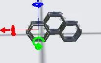
Module Topology
Each module will have 6 motors arranged in a fashion that they push down on fluid pouches, partially on the motors side and partially over an edge, like so:
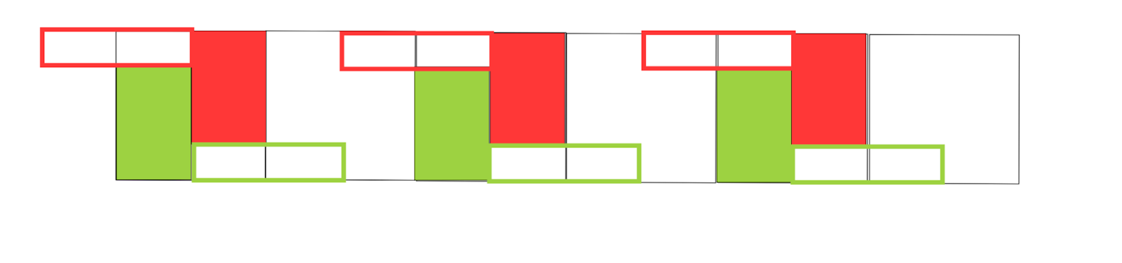
The outlined sections are parts of the fluid pouch over an edge, while the filled in sections represent the section that will get pressed down by a flat part. A video of this interaction is below:
PCB Design
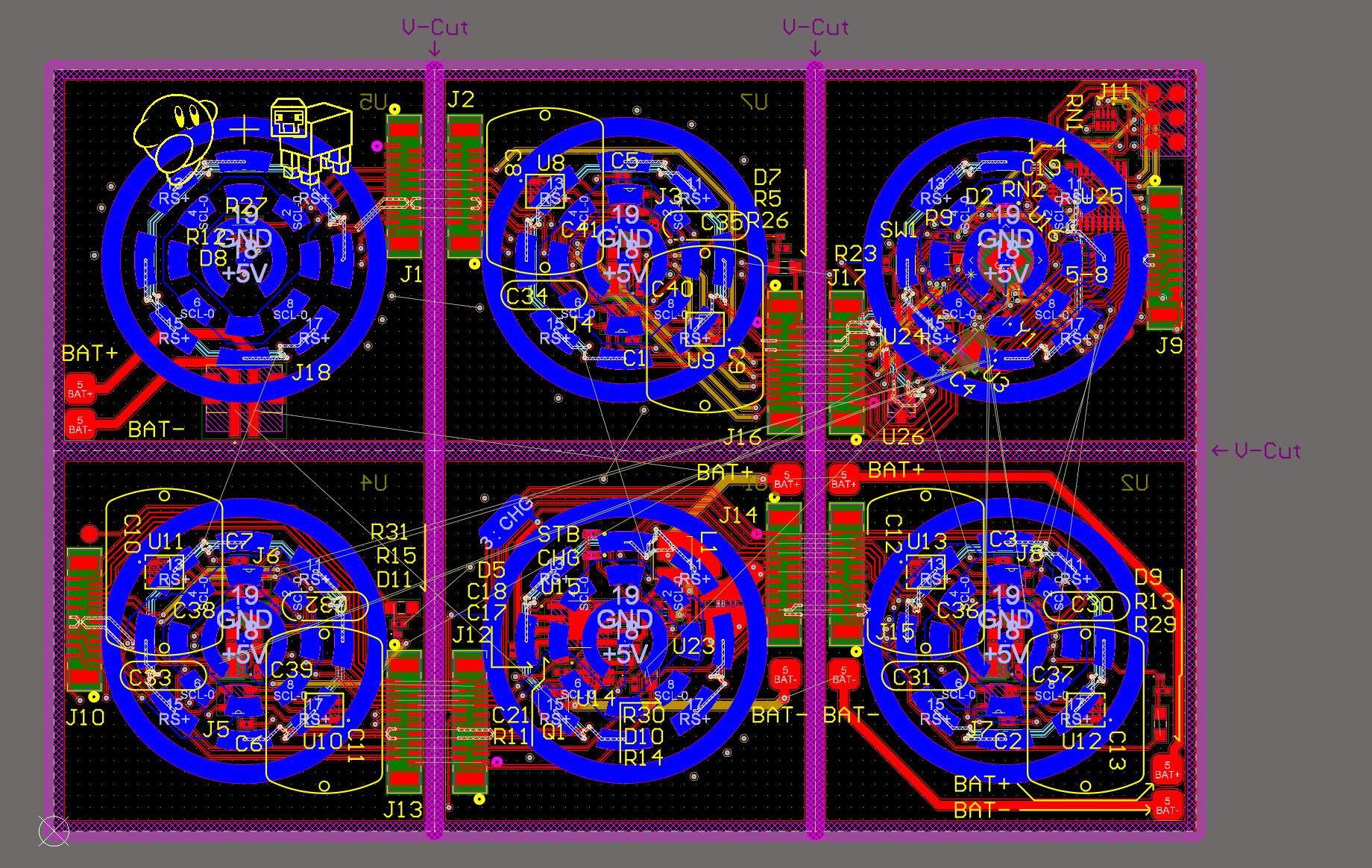
Next, we have the PCB design. A full schematic and 2D view of of the PCB is below:
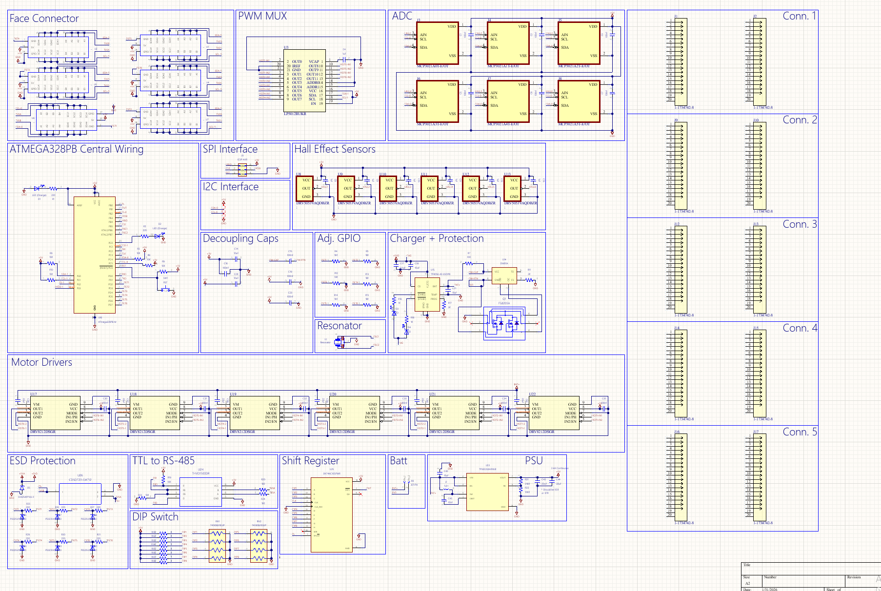
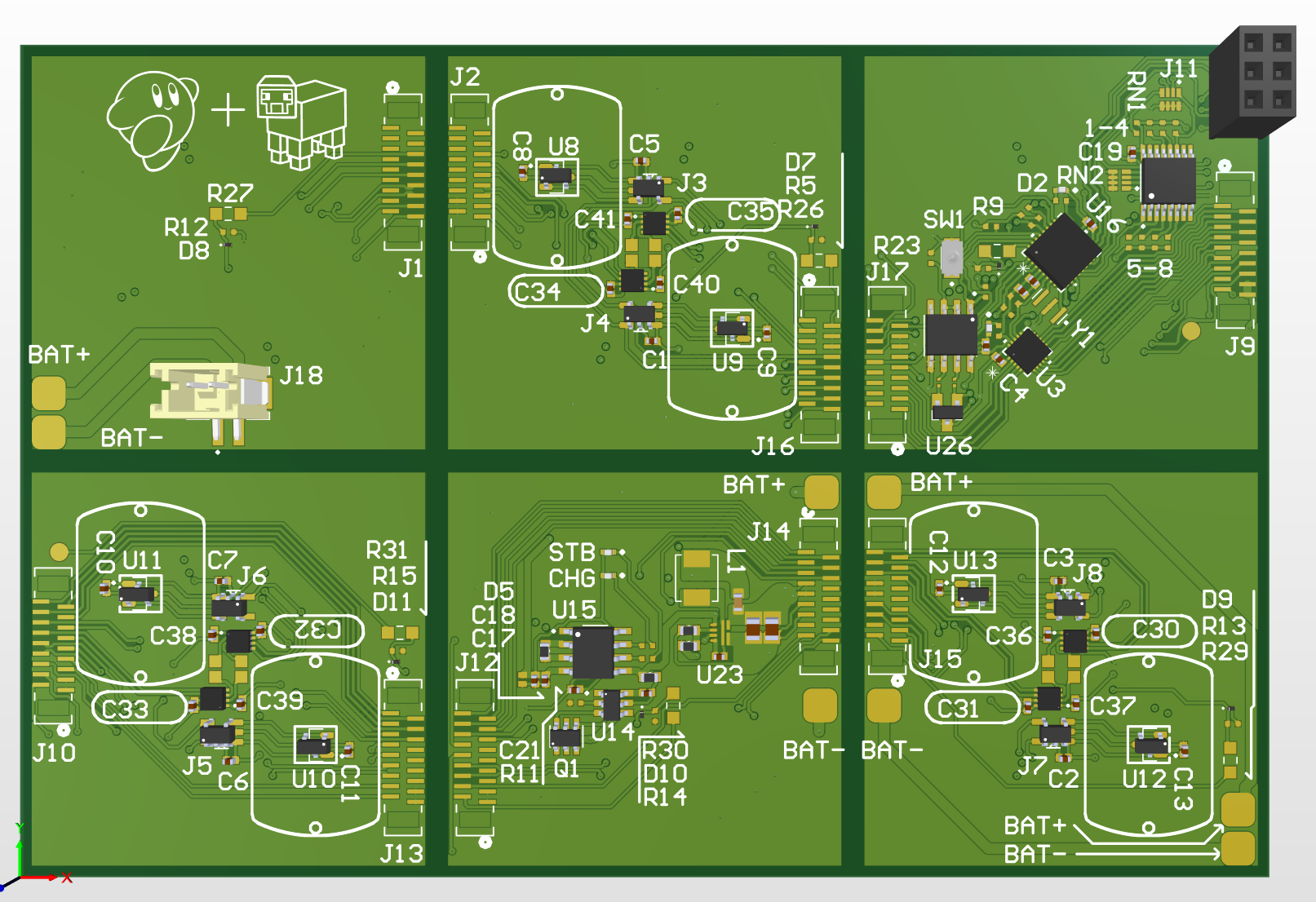
MCU
The microcontroller we're using for this project is the ATMega328PB (U16). Each module communicates with the system through wire (RS485 sneak peek!) so we don't need anything more complex. 2 I2C buses are exposed and 1 SPI bus is exposed for programming through ICSP, meaning we don't have to put an external FTDI chip on the board
Motor Drivers
To drive the 6 motors, we're using a TI type driver chip that can handle 4A. Each motor is driven at 5 volts, so there's ample power for every motor. Each motor driver needs 2 PWM signals, or 12 in total, so we use a PWM Mux that connects by I2C to the mainboard. (U3).
Feedback
To grab feedback on module position, we use a hall effect sensor under each place where the cam is going to press down. A magnet mounted in the follower mechanism means that we can reliably measure module position. This analog output is sent into a nearby ADC for each sensor, and all information is transported back across the I2C 0 line.
Power Distribution
Since a 1S battery (connected through J18) will power the whole system, there needs to be a way to bring that up to 5V. Using a TI TPS boost converter (u23), a DW01A protection chip, (u14), and a tp4056 batt charging ic (u15), we're able to have charging, protection, and 5V boost all in one package.
Interboard Connection
On the back of each module, there's a connection "face" made up of multiple levels of annular pads. (Looking at 2D PCB, it's the blue colored rings). We can transmit I2c, ground, power, and most importantly, RS485.
RS-485
Using an RS-485 transceiver we can have up to 128 loads on the entire system, and as each module gets snapped together (through 3M dual lock) we're able to have an intermeshed system that can talk to itself reliably.
DIP Switch
Using a shift register and 8 solderjumper pads, we're able to have an 8bit hardware id for each module. Upon boot, this is assigned to a wrapper ID by the master module, so you can take apart a whole system and reorganize it with different modules without any reprogramming.
GPIO Connection Detection
With 6 different GPIO pins, whenever a module is added to the system it sends out a signal on all of them, interrupting the module it was connected to. Since that module will already know it's position in the configuration, the master module can assign the new module a soft id and it can start working easily with the rest of the system.
Master Module
A master module made up of an ESP32 and transceiver will attach to a singular face of a singular module, allowing wireless communication with the whole system without raising cost.
Apply for sponsorship >>- Comments(0)
- Likes(1)