


Guitar Feedback Pedal Boost and Phase Reversal
About Us:
Hello, we are Cody C., Riley F., and Cecilia I., from Louisiana State University.
Outside of schooling, we were looking for ways to apply our class knowledge to practical applications. In this case, we wanted to evaluate and construct a boost and phase reversal circuit for a feedback guitar pedal to add more tone possibilities. Through our prototype testing we had very good results and learned a lot about analog circuit design in the process.
About
This is a build log and tutorial on how to build a simple feedback looper pedal. They are super simple to make, but open up so many tone possibilities to your arsenal. All you do is plug in a guitar into the input, route a pedal through the effects loop, and run the output to your signal chain or amp. Depending on the pedals put in the effects loop, like delay, fuzz, chorus, distortion, etc, you will have infinite delay, chasmic reverb, snarling fuzz tones, and so much more. Each pedal has a truly unique effect when placed in the looper that brings new life and inspiration to your guitar pedals.
Parts List
All of these parts can be easily picked up online for under 15-20 bucks.
This build can be made without the LED and DC jack, but I prefer having an indicator for whether the pedal is on.
- 1590BB Enclosure (I used a bigger enclosure for the graphics)
- 4x 1/4" Guitar Jacks
- 1x DC Power Connector
- 1x Latching or Momentary 3PDT Footswitch
- 1x LED
- 1x 4.7k resistor
For Boost and Phase Circuit
- 6x 1Meg Resistors
- 3x 10u Bipolar Capacitors
- 1x 47u Electrolytic Capacitor
- 1x 47p Capacitor
- 1x 2.7k Resistor
- 1x 4.7u Capacitor
- 1x TL072 OP Amp
- 3x 10k Resistors
- 1x C100k Potentiometer
- 1x A100k Potentiometer
- 1x Dual Gang Toggle Switch
- 1x Single Gang Toggle Switch
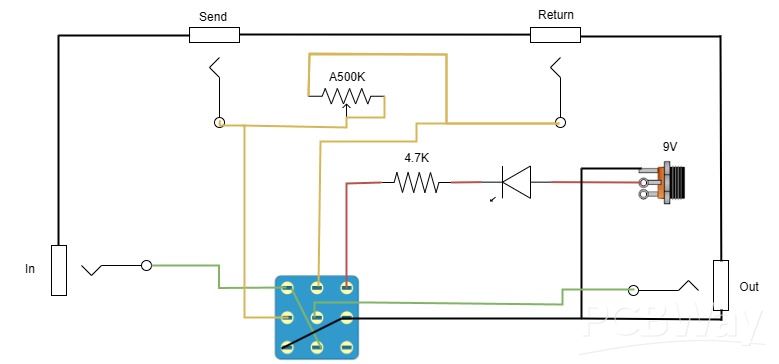
Schematic
This is the schematic for our original design of the feedback looper pedal without the boost and phase reversal circuit. The way this design works is by looping the effects loop back onto itself. Using a distortion pedal, feedback similar to amplifier feedback is observed. Whereas if you put a delay pedal in the loop, you can get infinite delay or a stacked delay effect. Every pedal will react differently in this setup, making for a truly unique pedal that brings new life to your pedals. As well as, with the volume potentiometer you can control how much feedback is being heard in the signal chain.
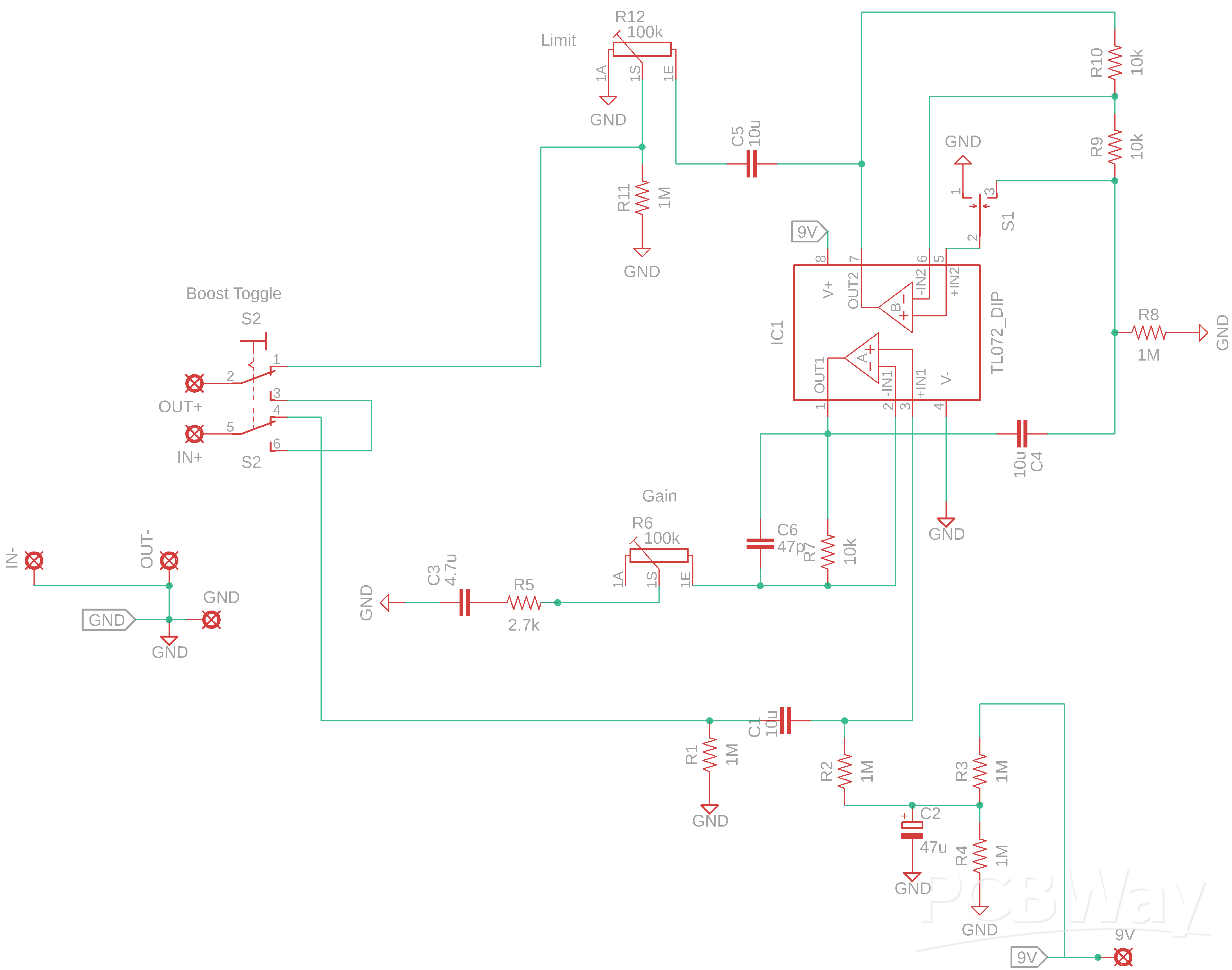
Boost and Phase Reversal Circuit
To increase versatility, we designed the schematic and circuit board for use with this pedal using LTSpice and Fusion 360. The design includes an adjustable clean boost, phase reversal, and adjustable feedback volume.
Analysis:
Clean boost stage
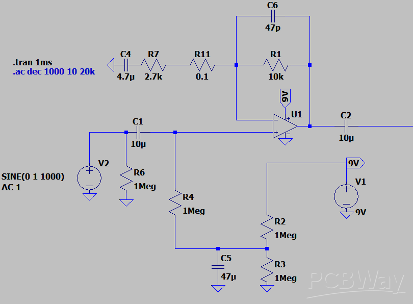
Cutoff Frequency Input and Feedback Loop
With a goal being a clean boost that will boost the feedback loop volume with a flat response, we used these components to get the cutoff frequency lower than a guitar's useable frequency range.
f = 2pi(10uF)(1Meg) = 0.02Hz
Cutoff Frequency Feedback Loop
f = 2pi(4.7uF)(2.7k) = 12.54Hz
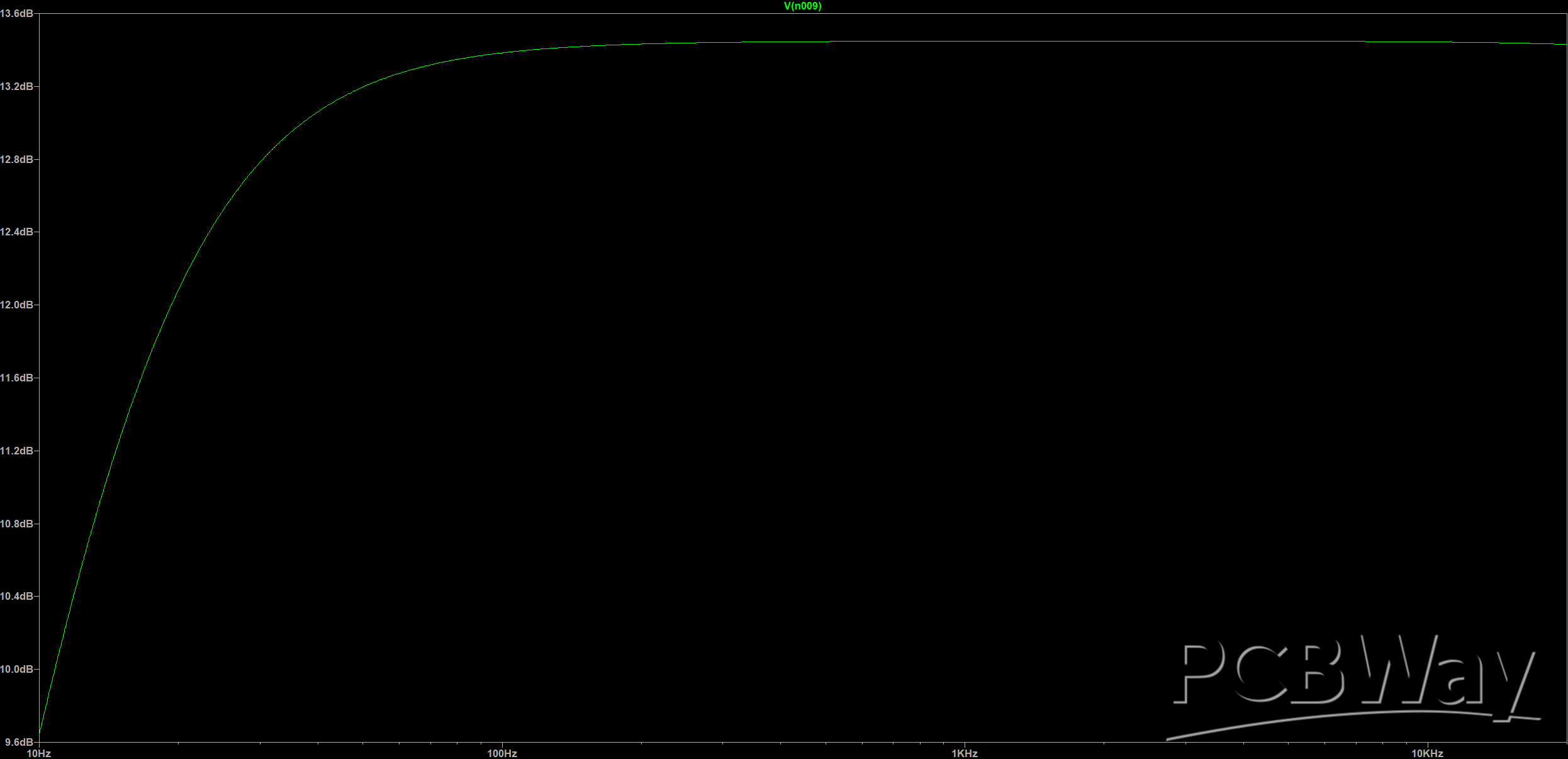
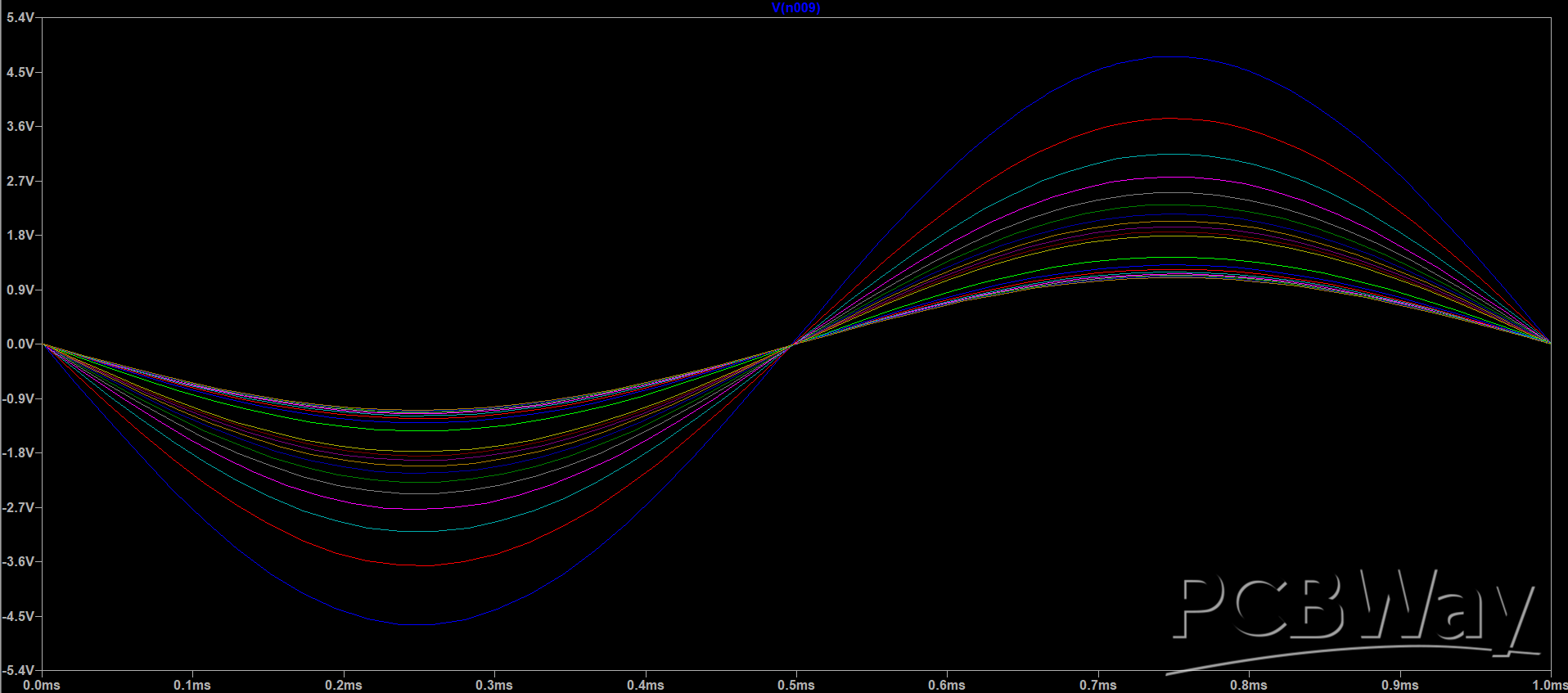
Gain
Since there will already be a considerable amount of feedback, we opted for a low gain boost. Since this is a clean boost you can see below there is not noticeable distortion or clipping of the output waveforms.
Gain = 1 + 10k / 2.7k = 4.7 Gain in dB = 20log(4.7) = 13.44dB
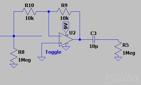
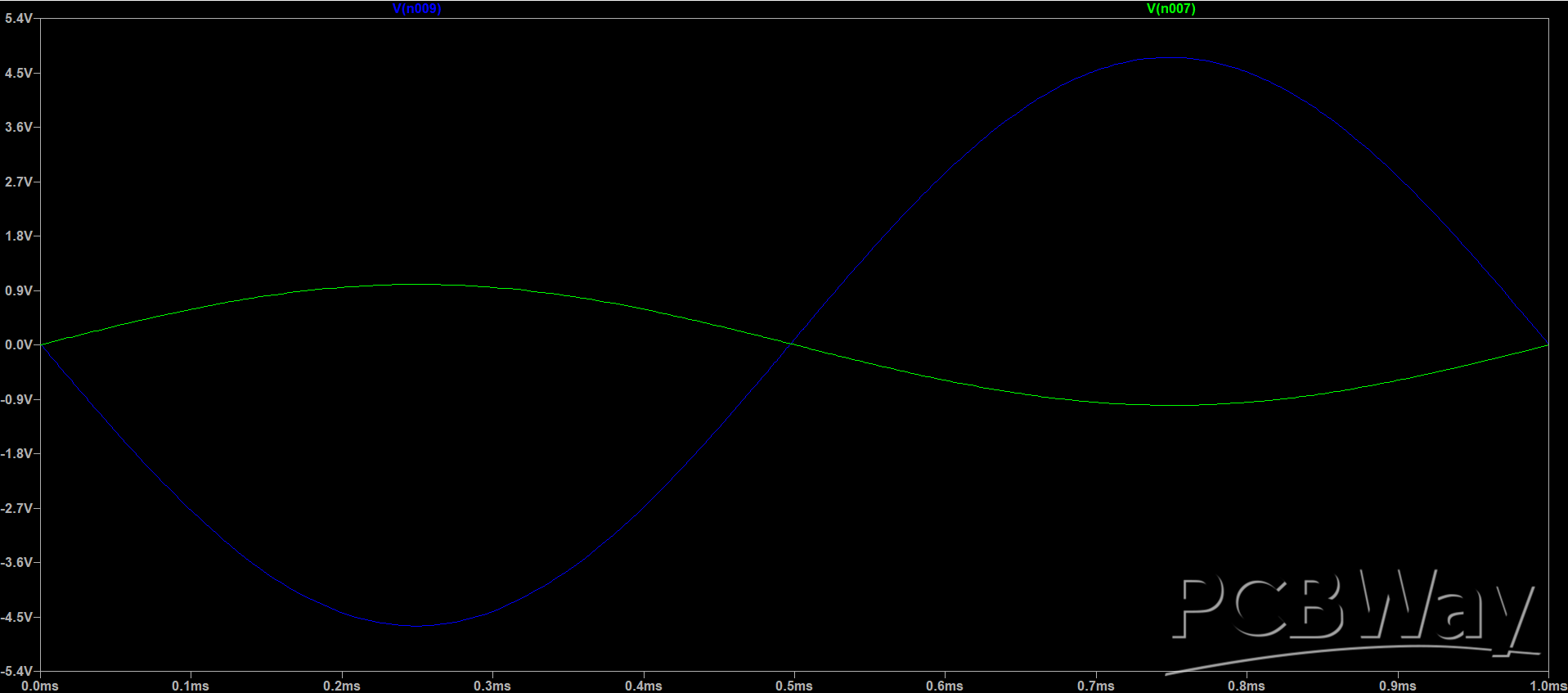
Phase Reverse and Buffer
To reverse the phase, we connected a toggle switch to the non-inverting input of the TL072 where the input is switched between positive boost output and ground. When switched to ground, the phase will be reversed 180 degrees and have a significant effect on the tone. Since the signal was boosted in the first stage, we used two 10k resistors for unitary gain.
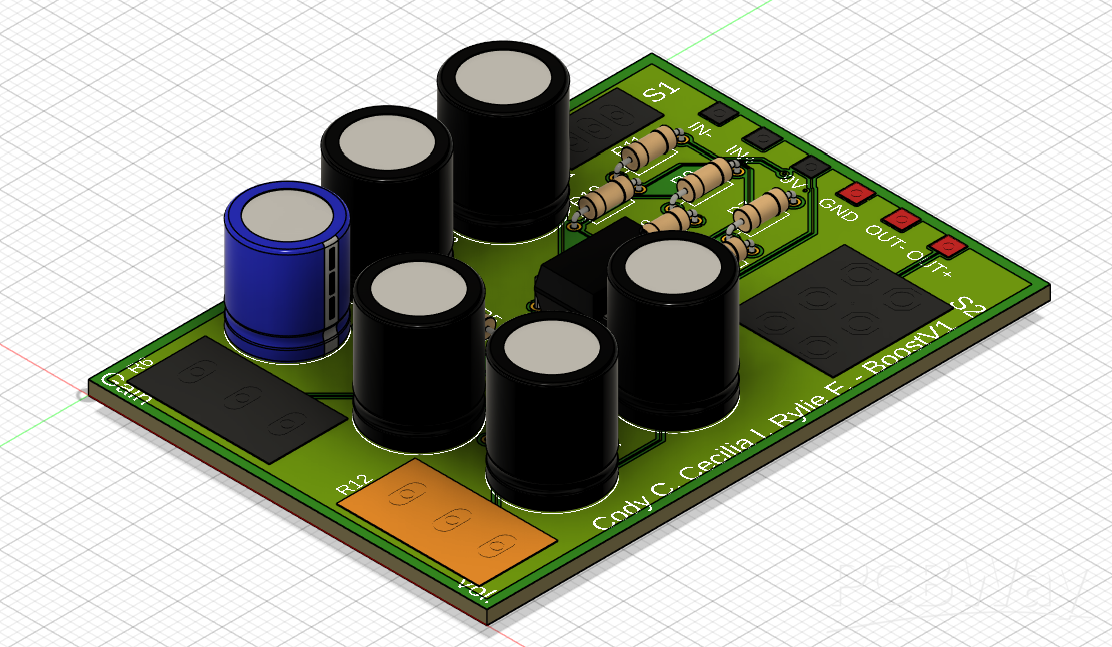
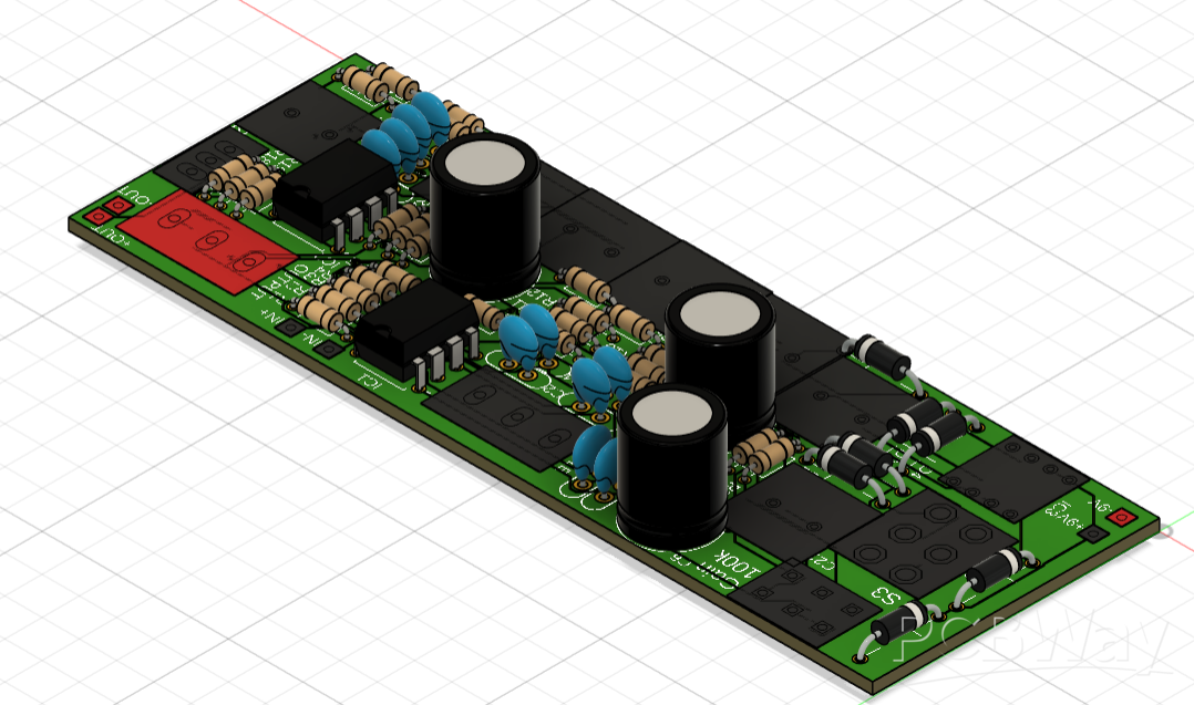
PCB Rendered
This is a 3D model of the circuit board we intend on fabricating.
Closing Remarks
As you can see, the feedback pedal is a simple yet effective way to add so much tonal versatility to your guitar playing.
We appreciate how PCBWay has provided professional solutions to students and electronics enthusiasts, and we believe that their sponsorship would be essential to easy and reliable construction of the feedback looper. It would be an honor to share the results with the PCBWay community and contribute my project to their platform, as well as inspire more hobbyists like us to experiment with electronics.
Whether it’s school or personal projects, We driven by the desire to create technology that makes a difference and improve my skills. If you’re interested in collaborating or discussing anything further, lets connect to talk about it.
Thank you very much for your time and consideration!
Apply for sponsorship >>- Comments(0)
- Likes(0)
 More by Cody Carter
-
 Guitar Feedback Pedal Boost and Phase Reversal
About Us:Hello, we are Cody C., Riley F., and Cecilia I., from Louisiana State University. Outside o...
Guitar Feedback Pedal Boost and Phase Reversal
About Us:Hello, we are Cody C., Riley F., and Cecilia I., from Louisiana State University. Outside o...
-
 Klon Centaur Guitar Pedal
About Me:Hello, I’m Cody Carter, a Computer Engineering student at Louisiana State University. My pa...
Klon Centaur Guitar Pedal
About Me:Hello, I’m Cody Carter, a Computer Engineering student at Louisiana State University. My pa...
-
 Dallas Rangemaster Guitar Pedal
About Me:Hello, I’m Cody Carter, a Computer Engineering student at Louisiana State University. My pa...
Dallas Rangemaster Guitar Pedal
About Me:Hello, I’m Cody Carter, a Computer Engineering student at Louisiana State University. My pa...
-
 DIY ESP32 Powered RC Car
About Us:Hello, we are Cody Carter and Ethan Fenton, Computer Engineering students at Louisiana Stat...
DIY ESP32 Powered RC Car
About Us:Hello, we are Cody Carter and Ethan Fenton, Computer Engineering students at Louisiana Stat...
-
 DIY Fuzz Face Guitar Pedal
About Me: Hello, I’m Cody Carter, a Computer Engineering student at Louisi...
DIY Fuzz Face Guitar Pedal
DIY Fuzz Face Guitar PedalAbout Me: Hello, I’m Cody Carter, a Computer Engineering student at Louisi...


