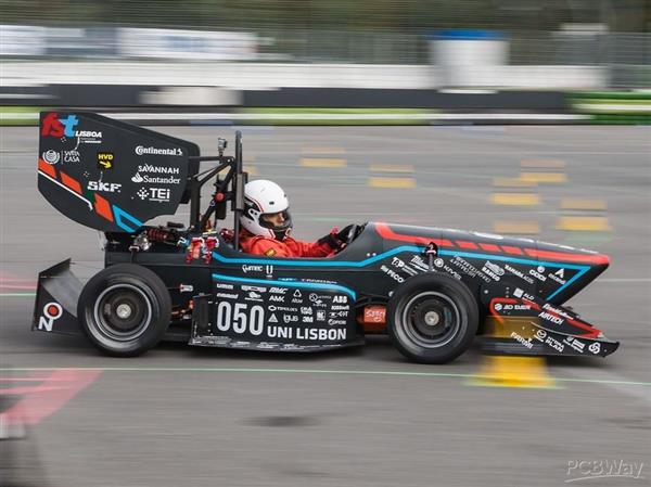
FST Lisboa - Electric Project

The team at the biggest engineering competition in the world. @FSG.
About the team:
FST Lisboa is the Formula Student team from Instituto Superior Técnico, University of Lisbon.
Since 2001 we’ve been constantly reviewing and refining what we do to deliver the very best output and respond to the demands of an ever changing motorsport industry.
If in the beginning the goal of only 10 students was to create a relatively seamless combustion prototype, now we’re 40 students organized in 2 different projects: Electric and Driverless.
FST 10e
All the car's PCBs (over 20) are designed by the team. This is done in order to have more control on the electronic’s architecture. The latest prototype from the electric team aims to improve on what FST 09e (the previous car) was. Since it now has a stable basis on which to work on, to improve on the details and increase performance, the team now needs more information on the car's behaviour to push it to the limits. With that in mind, a big emphasis was placed on
information accessibility as well as sensor integration. Measurements such as brake caliper temperature and cooling tube's temperature will be integrated on the future car.
One other big component of Formula Student is the tight regulation, with even tighter inspection. Taking that into account, our safety systems must be design and manufactured in the most reliable way.
Our PCBs
As said before, we design all our PCBs, which range from essential control, sensors and high voltage. These PCBs are designed in Altium and suffer an intense review from our alumni (former team members) before being sent into production.
BMS Slave
Since FST 10e has Li-Ion battery, it needs a BMS (Battery Management System). This PCB was developed with the intent of measuring the temperature and voltage of a portion of the battery, 28 cells. It also handles the balancing of the cells, in other words, guarantees that the cell voltage is homogeneous throughout the battery.

CCU
In order to cool our (very hot) motors and inverters, a cooling circuit was designed, based on pumps and radiators fans. The cooling components have a very high energy consumption and are oversized for our application. Therefore, the CCU's (Cooling Control Unit) purpose is to measure the temperature of the cooling circuit and regulate the operating PWM optimally.
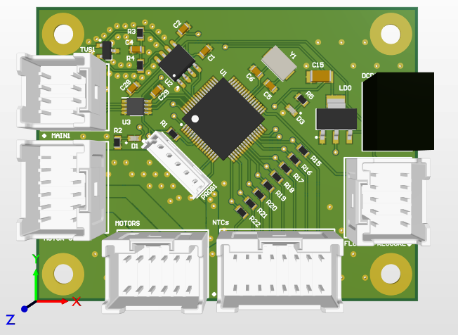
TE
The car's control resides on its pedals. The accelerator is equipped with potentiometers that control the torque being sent to the motors. In addition to the potentiometers, the brake pedals also have a pressure sensor. The TE (Torque Encoder) PCB ensures that the safety guidelines are being followed. For example, if by any chance the pilot is braking and accelerating at the same time, the motors shouldn't receive torque for safety reasons.

Support from PCBWay would unlock a more in-depth prototyping phase. Since we are very restricted in terms of support, when faced with a small error in a PCB the module is sometimes discontinued due to lack of budget. If we could quickly and reliably prototype our boards, it would have a big impact on our prototype's performance.
- Comments(0)
- Likes(0)