


DIY Arduino RC Receiver
In this tutorial we will learn how to make an Arduino based RC receiver. Since building my DIY Arduino RC transmitter in one of my previous videos, I got a lot of requests from you guys, to make a dedicated receiver for it, so here it is.
Now these two devices can easily communicate and we can use them for controlling many things wirelessly. I will explain how everything works through few examples. In the first example we will use this Arduino RC receiver to control a simple car consisting of two DC motors. In the second example I will show you how to control brushless motors and servos, which are common components found in many commercial RC planes, boats, cars and so on. If we know how to control them, we can easily modify and control many RC models with our own custom-build Arduino transmitter.
![]()
As a third example I will show you how I modified and used this Arduino based RC system to control a commercial RC car.
Arduino RC Receiver Circuit Diagram
To begin with, let’s take a look at the circuit diagram of this system. The radio communication is based on the NRF24L01 transceiver modules.
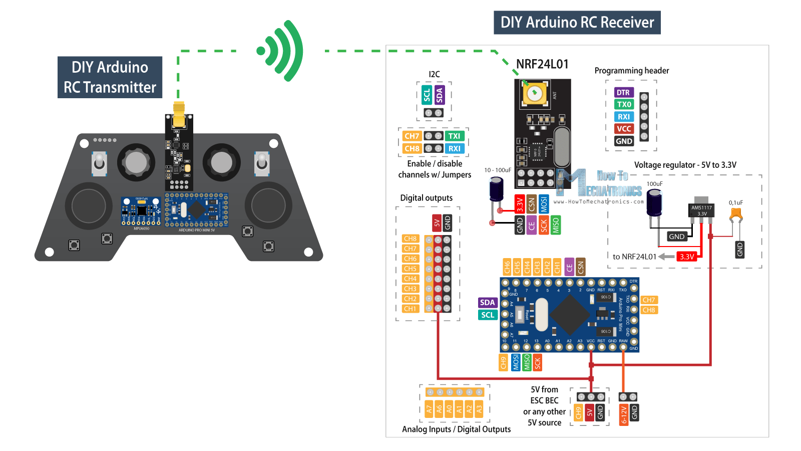
The transmitter constantly sends data from its controllers, the joysticks, the buttons, the potentiometers and the toggle switches, and we receive this data with the receiver. For more details how this Arduino transmitter works you can check my other detailed tutorial for it.
We can also note here that this RC receiver doesn’t necessarily work with only this particular Transmitter that I built. It can work with any other similar setup consisting of an Arduino board and a NRF24L01 module.
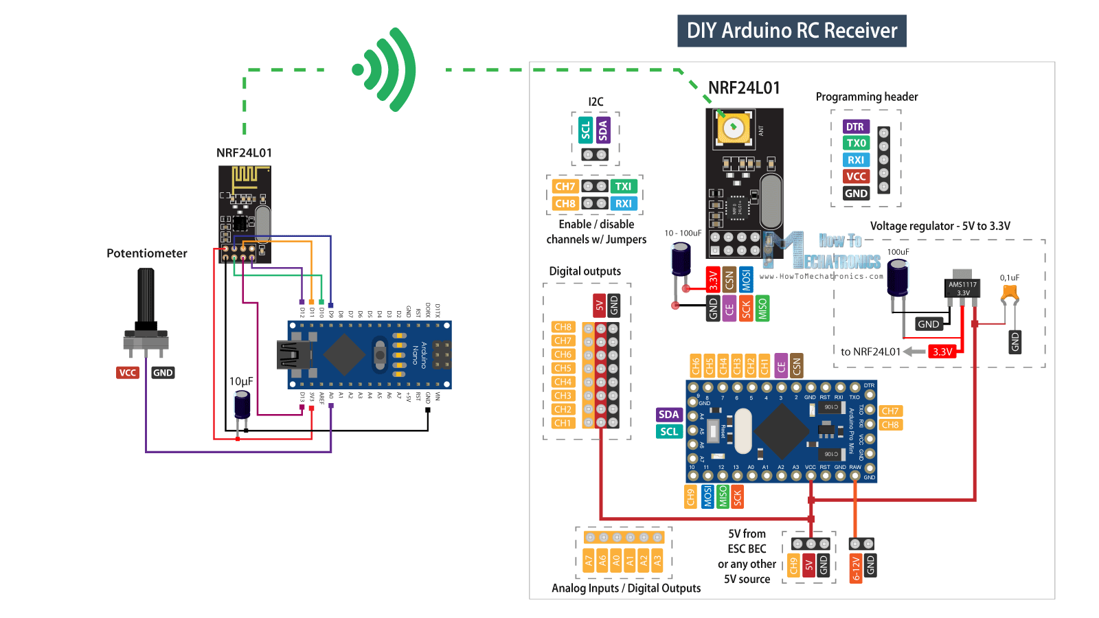
Nevertheless, the brain of this RC receiver is an Arduino Pro Mini board. For powering, we can either use the VCC pin to which we can connect 5V, or the RAW pin to which we can connect from 6 to 12V. Note that there are two versions of the Arduino Pro Mini, like the one I use here that operates at 5V and the other operates at 3.3V. On the other hand, the NRF24L01 module operates at 3.3V, so therefore we need a voltage regulator. This time I’m using the AMS1117 voltage regulator, which outputs 3.3V from inputs which can range from 5V to 12V.
You can get the components needed for this Arduino RC Receiver from the links below:
- NRF24L01 Transceiver Module…….……… Amazon / Banggood
- NRF24L01 + PA + LNA …………………..……. Amazon / Banggood
- AMS1117 3.3V Voltage regulator ……….. Amazon / Banggood
- Pin Headers Male + Female ……………….. Amazon / Banggood
- Arduino Pro Mini………………..……..……….. Amazon / Banggood
- Arduino Pro Mini like the one I used…… Ebay
Disclosure: These are affiliate links. As an Amazon Associate I earn from qualifying purchases.
For communication with the Arduino, the NRF24L01 module uses the SPI protocol, plus two additional digital pins. That means we are left with 9 digital pins which can be used as output channels, two of which are the RX and the TX pins. It’s worth noting, that these pins must be disconnected from anything while we are uploading a sketch to the Arduino board, so therefore I made it possible to be connected or disconnected through separate pin headers. Actually, we can also use the analog inputs as digital outputs, so although this Arduino board is quite small, we got plenty of outputs or channels available.
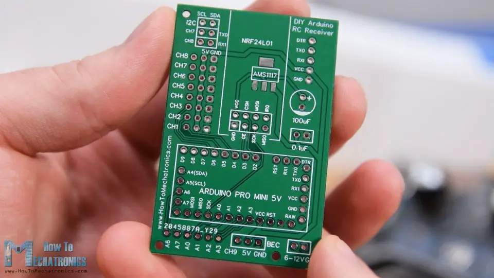
PCB Design
Nevertheless, in order to keep this circuit compact, I made a custom PCB using the EasyEDA free online circuit design software. Here, I arranged the 8 channels right next to a 5V and a Ground rail, and so we can directly connect servos and ECSs to them. The channel number 9 is located at a separate position, near the VCC pin of the Arduino, so we can use for example, an ESC for powering the Arduino with its Battery Eliminator Circuit feature which provides 5V. Of course, we could use any other channels for that purpose, as the VCC pin is connected to those 5V rail as well.
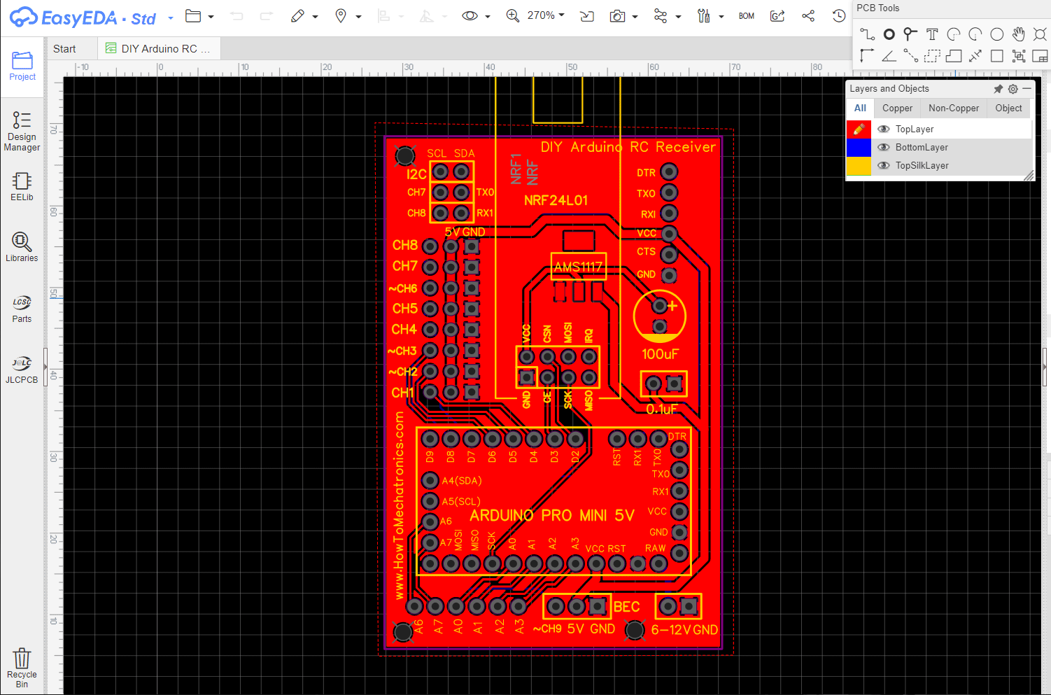
As for the channels number 7 and 8, we can see here how there are interrupted with these pin headers. If we want to use them, we just have to connect the two pins together. The programming header is located at the top right corner and the 100uF capacitor serves for both the voltage regulator and the NRF24L01 module. On the bottom left corner of the PCB, I placed the analog pins.
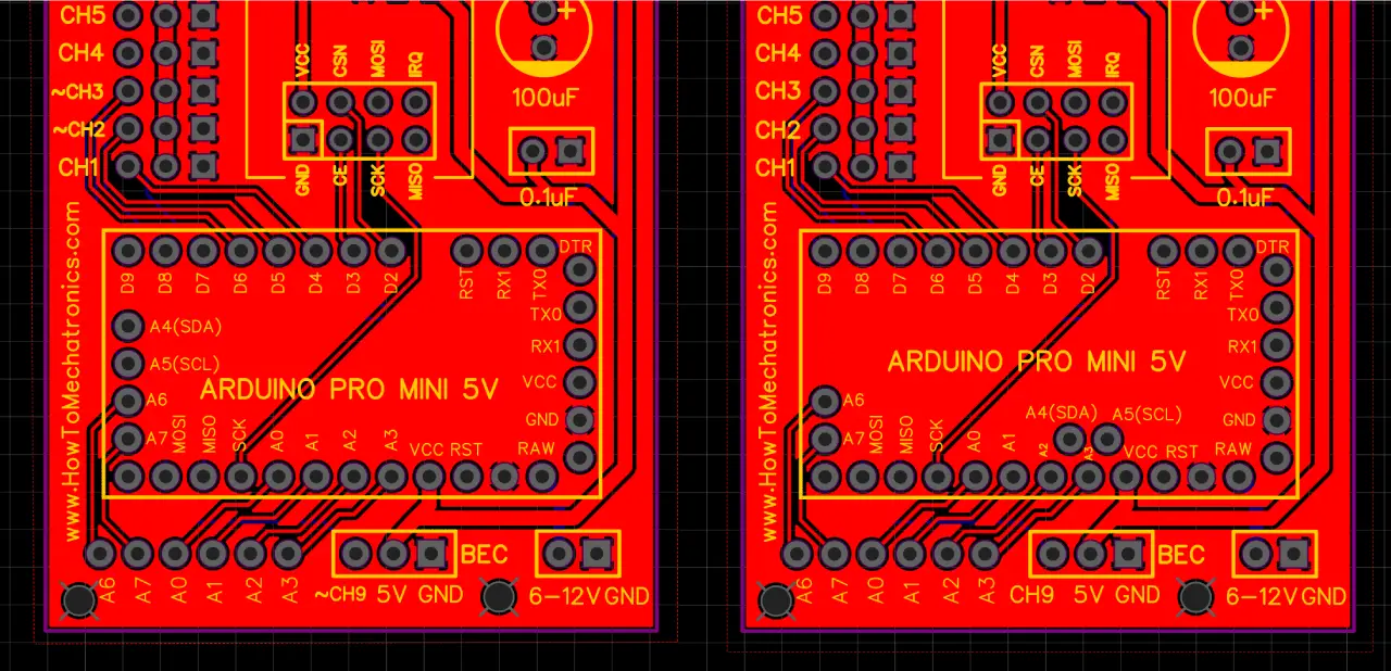
Here we can note one more thing, and that’s that some Arduino Pro Mini boards might have different pins arrangement, so therefore I included one more version of the PCB so you can choose the one that match with your Arduino Pro Mini board.
Now we can move on and assemble the PCB. First, we need to solder the pin headers of the Arduino board. A convenient way to do that is to use a breadboard to stick the pin headers in it and so the board will stay firmly in place while soldering. As I said earlier, depending on your board, the pins might vary a bit, so keep that in mind when soldering them.
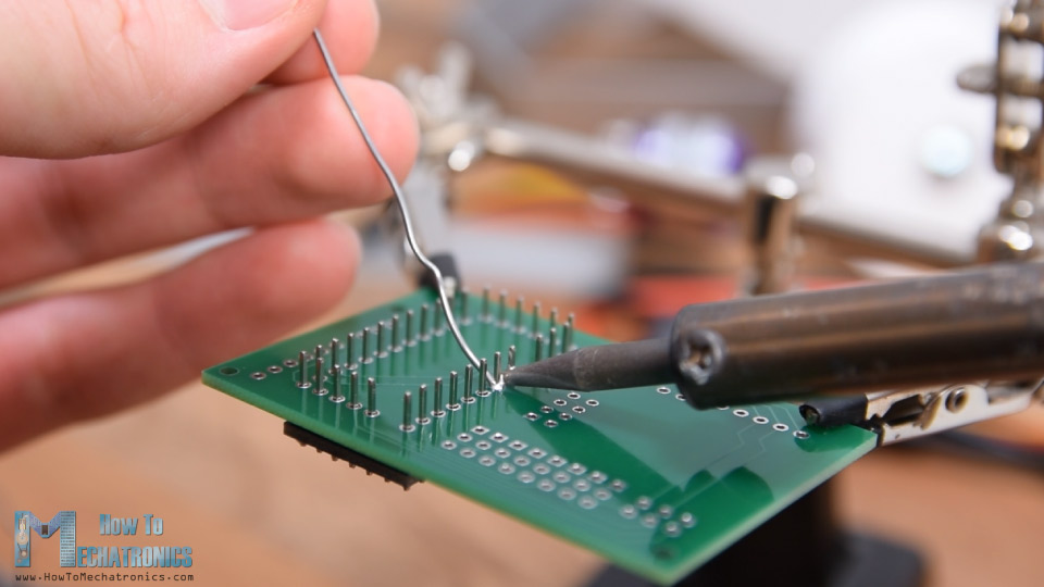
Also, there are some Ground pins that we need to leave free as there are some traces running on the PCB under them. Once I soldered the Arduino board, I cut the excess length off the pins.
Next, I placed all other pin headers in place. We need both male and female pin headers, or it’s actually up to you what pin headers you will choose to use. However, it’s good idea to use male pin headers for the digital channels as the servo motors and the ESC connections are female, so we can easily connect them.
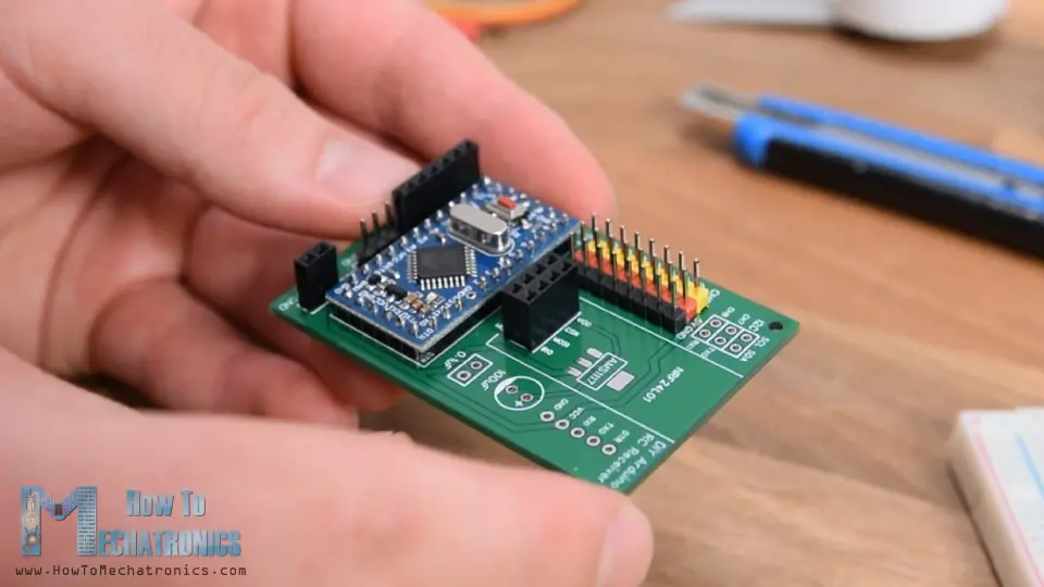
The voltage regulator is a surface mount component so I used some Blue-Tack adhesive to hold it in place while soldering. Lastly, once we solder the two capacitors in place, we can attach the NRF24L01 module to the appropriate pin headers.
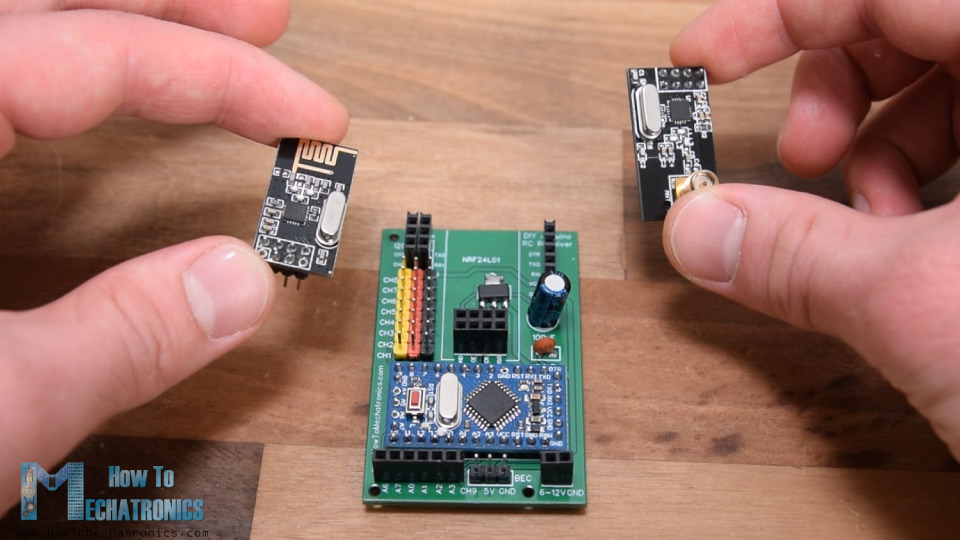
Depending on the application, or the range that we need, we can use either the normal module with the on-board antenna, or the one to which we can attach a bigger antenna and can achieve wireless communication of up to 700 meters in open space. So that’s it, our Arduino RC Receiver is now ready and we can use it for anything we want.
For programming the receiver, or connecting the Arduino Pro Mini to the computer, we can use an USB to serial UART interface which can be connected to the programing header.
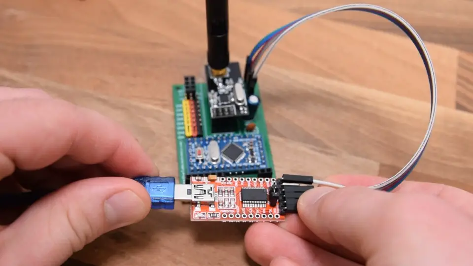
In the Arduino IDE tools menu we need to select the Arduino Pro or Pro Mini board, select the proper version of the processor, select the port and select the programming method to “USBasp”.
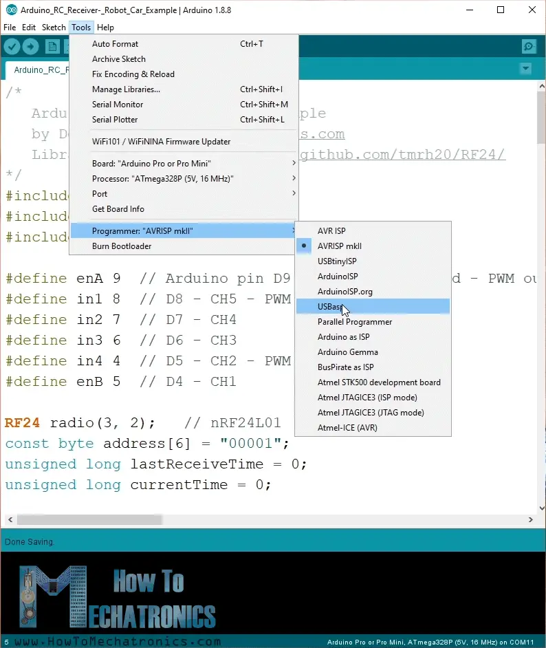
And so now we are able to upload codes to the Arduino.
Example 1 – Arduino RC Car
Ok, now we can move on and take a look at the first example.
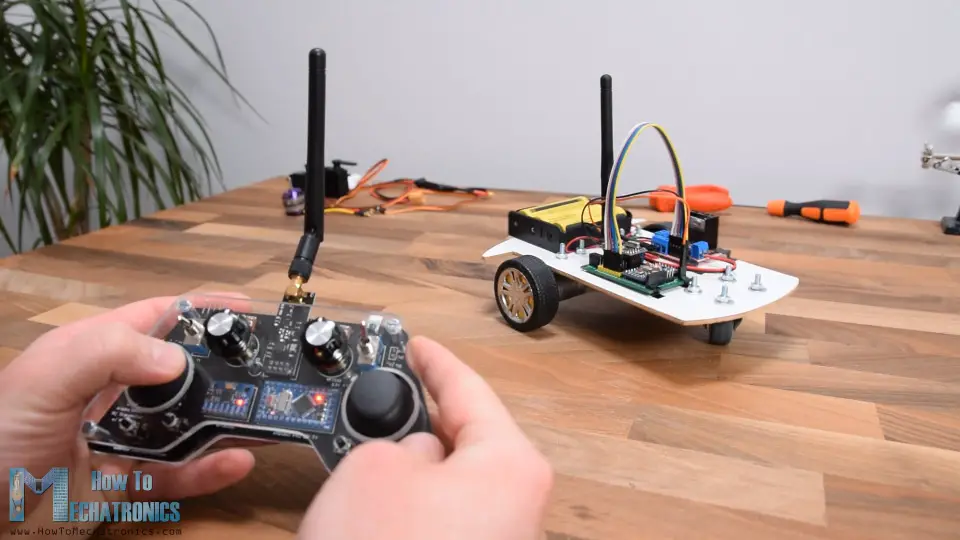
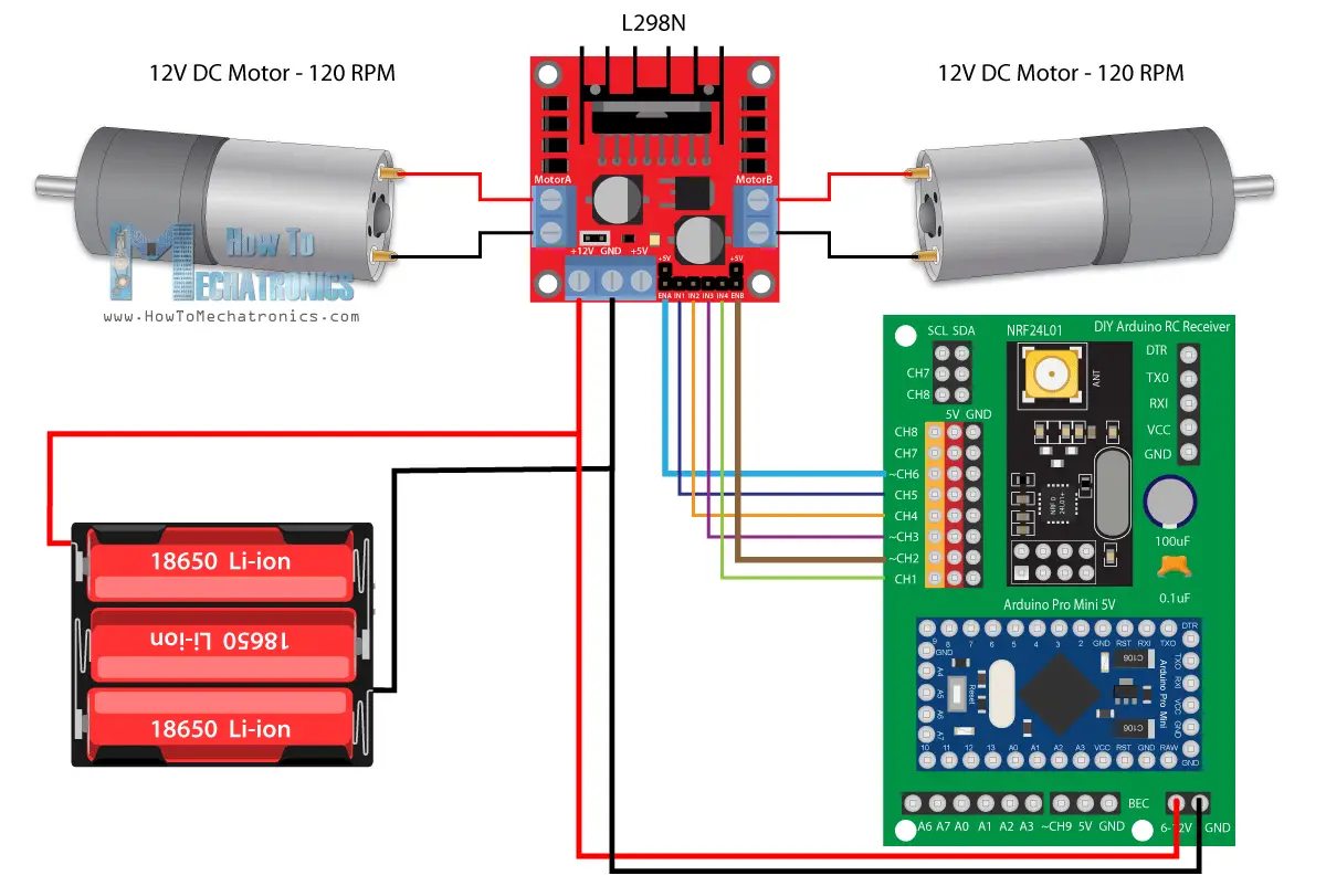
It’s a simple car consisting of two 12V DC motors and in some of my previous videos I have already showed you how it works and how to build it.
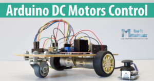
Arduino DC Motor Control Tutorial – L298N | PWM | H-Bridge
This time we will use our new Arduino RC receiver for controlling it. For driving the DC motors, we are using the L298N motor driver and for powering, we are using 3 Li-ion batteries which provide around 12V.
You can get the components needed for this example from the links below:
- L298N Driver ……………………………….. Amazon / Banggood
- 12V High Torque DC Motor ………….. Amazon / Banggood
- DC Motor w/ Plastic Tire Wheel ……. Amazon / Banggood
- Breadboard and Jump Wires ………… Amazon / Banggood
Disclosure: These are affiliate links. As an Amazon Associate I earn from qualifying purchases.
So, the connections are really simple, the 12V coming from the batteries go the 12V pin on our receiver, and the six control pins of the driver go to the 6 channels. We need to note here that in order to be able to control the speed of the motors we need to provide PWM signal to the Enable A and Enable B pins of the driver. In our receiver the channels number 2, 3, 6 and 9 can output PWM signals, so there I connected the Enable pins of the driver to the channels number 2 and 6 in this case.
- Comments(2)
- Likes(2)


