Actively Controlled Rocket using Canards - Hyades
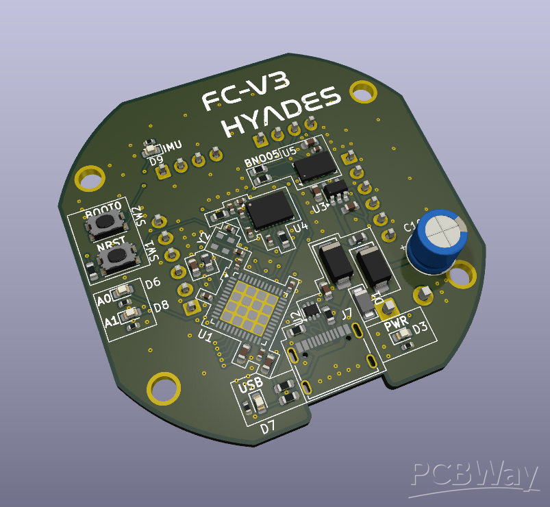
Pictured is 3rd Iteration of the flight computer design.
I am a first year A-Level student studying to go into the aerospace industry. Recently I have been developing a canard controlled rocket with the goal of having full attitude control. So far I have prototyped the basic electronics and software using breakout boards and 3D prints. This is a video of a test I did on my YouTube channel recently:
Here is a integration test I did a few weeks ago, testing the sensor fusion algorithms and LQR controller. The current goal is to produce a 60mm Diameter rocket as this allows me to minimise weight and launch cost as well as providing a more challenging physical design. While I initially tried to produce a rocket in 50mm diameter, I quickly realised this would not be feasible using the current direct drive servo configuration. In the future linear actuators could potentially be used to further reduce the diameter to fit this initial goal.
When I first started researching this project, I had no idea how to try and design PCB's, this led to this:
However I failed to account for the fact that I would need to solder the SMD components on by hand - this did not go well - so I ended up with a waste bag of parts and some spare PCB's, as well as likely numerous design issues on the board. Since then I have done more research and actual physical prototyping as seen and I now feel that just using breakout boards is starting to become a limiting factor in how far I can keep developing this design. The current design is relatively simple:
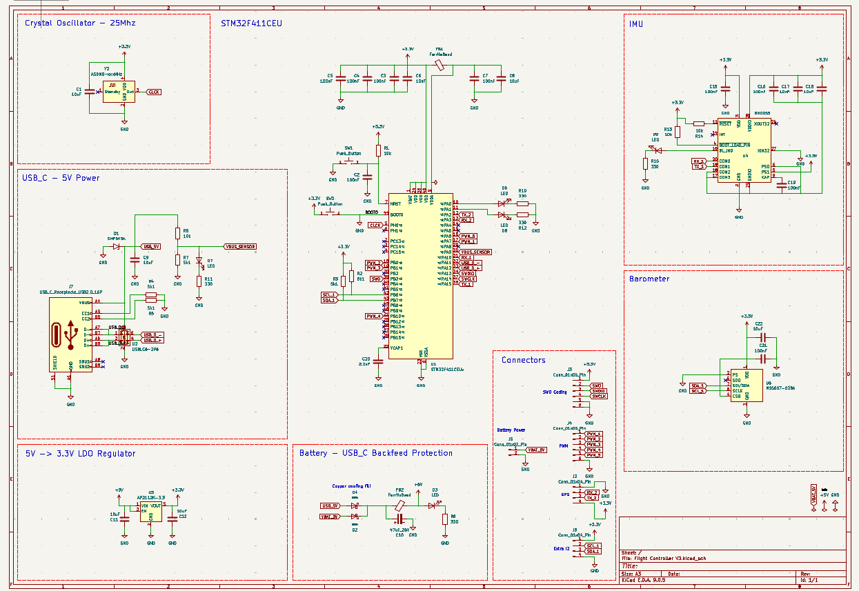
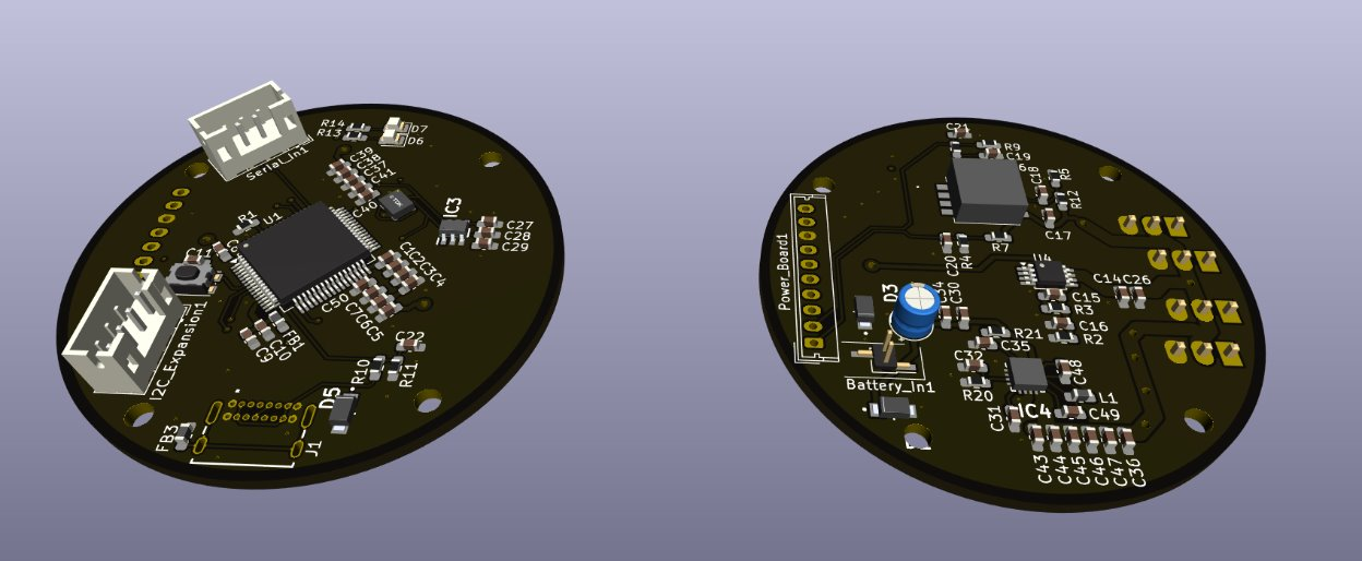
I am utilising a commercially available PDB to regulate the 2S LiPo Voltage into a steady 5V and then distribute it to 4 servo's, each controlling a canard respectively. Then on the PCB, there is a 3.3V LDO Regulator, providing the voltage for the MCU and sensors. These include the BNO05, chosen because it integrates a sensor fusion algorithm into itself, saving a significant amount of software development time, and a Barometer and GPS to provide more accurate altitude and global position estimates. Most of the general CAD modelling has now been done:
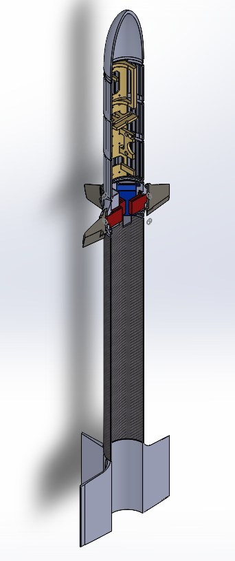
Which I hope to use in simulation software such as ANSYS to better tune the controller gains and improve the aerodynamics of the rocket to reduce the chance of damage on the first flight. The frontal section including avionics bay will be 3D printed, with the final product likely using a stronger engineering filament such as PA-CF. The Design shown above is using the breakout board avionics sled, leading to a significant (~30%) mass increase over what could be done with a compact custom PCB based design.
Thanks for reading. A Sponsorship by PCBWay would mean a massive amount to me as it would allow me to continue developing a more lightweight, efficient and reliable system, without being so limited by pre-existing breakout boards and hopefully inspire others to become engineers.
Apply for sponsorship >>- Comments(0)
- Likes(1)