


555 led rumnning
The 555 timer IC is an integral part of electronics projects. Be it a simple project involving a single 8-bit micro-controller and some peripherals or a complex one involving system on chips (SoCs), 555 timer working is involved. These provide time delays, as an oscillator and as a flip-flop element among other applications.
Introduced in 1971 by the American company Signetics, the 555 is still in widespread use due to its low price, ease of use and stability. It is made by many companies in the original bipolar and low-power CMOS types. According to an estimate, a billion units were manufactured back in the year 2003 alone.
Depending on the manufacturer, the standard 555 timer package includes 25 transistors, 2 diodes and 15 resistors on a silicon chip installed in an 8-pin mini dual-in-line package (DIP-8). Variants consist of combining multiple chips on one board. However, 555 is still the most popular. Let us look at the pin diagram to have an idea about the timer IC before we talk about 555 timer working.
555 ടൈമർ ഐസി ഇലക്ട്രോണിക്സ് പ്രോജക്റ്റുകളുടെ അവിഭാജ്യ ഘടകമാണ്. ഒരൊറ്റ 8-ബിറ്റ് മൈക്രോ കൺട്രോളറും ചില പെരിഫെറലുകളും ഉൾപ്പെടുന്ന ഒരു ലളിതമായ പ്രോജക്റ്റ് അല്ലെങ്കിൽ ചിപ്പുകളിലെ സിസ്റ്റം (SoCs) ഉൾപ്പെടുന്ന സങ്കീർണ്ണമായ ഒന്ന് ആകട്ടെ, 555 ടൈമർ ജോലി ഉൾപ്പെടുന്നു. ഓസിലേറ്റർ എന്ന നിലയിലും മറ്റ് ആപ്ലിക്കേഷനുകൾക്കിടയിൽ ഒരു ഫ്ലിപ്പ്-ഫ്ലോപ്പ് ഘടകമായും ഇവ സമയ കാലതാമസം നൽകുന്നു. 1971 ൽ അമേരിക്കൻ കമ്പനിയായ സിഗ്നെറ്റിക്സ് അവതരിപ്പിച്ച 555 അതിന്റെ കുറഞ്ഞ വില, ഉപയോഗ സ ase കര്യം, സ്ഥിരത എന്നിവ കാരണം ഇപ്പോഴും വ്യാപകമായ ഉപയോഗത്തിലാണ്. ഒറിജിനൽ ബൈപോളാർ, ലോ-പവർ സിഎംഒഎസ് തരം പല കമ്പനികളും ഇത് നിർമ്മിക്കുന്നു. ഒരു കണക്കനുസരിച്ച്, 2003 ൽ മാത്രം ഒരു ബില്യൺ യൂണിറ്റുകൾ നിർമ്മിക്കപ്പെട്ടു. നിർമ്മാതാവിനെ ആശ്രയിച്ച്, സ്റ്റാൻഡേർഡ് 555 ടൈമർ പാക്കേജിൽ 8 പിൻ പിൻ ഡ്യുവൽ-ഇൻ-ലൈൻ പാക്കേജിൽ (ഡിഐപി -8) ഇൻസ്റ്റാൾ ചെയ്ത സിലിക്കൺ ചിപ്പിൽ 25 ട്രാൻസിസ്റ്ററുകൾ, 2 ഡയോഡുകൾ, 15 റെസിസ്റ്ററുകൾ എന്നിവ ഉൾപ്പെടുന്നു. ഒരു ബോർഡിൽ ഒന്നിലധികം ചിപ്പുകൾ സംയോജിപ്പിക്കുന്നതാണ് വേരിയന്റുകൾ. എന്നിരുന്നാലും, 555 ഇപ്പോഴും ഏറ്റവും ജനപ്രിയമാണ്. 555 ടൈമർ വർക്കിംഗിനെക്കുറിച്ച് സംസാരിക്കുന്നതിന് മുമ്പ് ടൈമർ ഐസിയെക്കുറിച്ച് ഒരു ധാരണ ലഭിക്കുന്നതിന് പിൻ ഡയഗ്രം നോക്കാം.
the circut for make oslation

out put configured as led dimminh 1hz
c1=10uf
ra=22k
rb=10k 1-3hz wave genarating
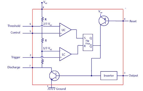
block diagram 555
PinNamePurpose 1 GND Ground reference voltage, low level (0 V) 2 TRIG The OUT pin goes high and a timing interval starts when this input falls below 1/2 of CTRL voltage (which is typically 1/3 Vcc, CTRL being 2/3 Vcc by default if CTRL is left open). In other words, OUT is high as long as the trigger low. Output of the timer totally depends upon the amplitude of the external trigger voltage applied to this pin.
3 OUT This output is driven to approximately 1.7 V below +Vcc, or to GND. 4 RESET Advertisement
A timing interval may be reset by driving this input to GND, but the timing does not begin again until RESET rises above approximately 0.7 volts. Overrides TRIG which overrides threshold.
5 CTRL Provides “control” access to the internal voltage divider (by default, 2/3 Vcc).
6 THR The timing (OUT high) interval ends when the voltage at threshold is greater than that at CTRL (2/3 Vcc if CTRL is open).
7 DIS Open collector output which may discharge a capacitor between intervals. In phase with output.
8VccPositive supply voltage, which is usually between 3 and 15 V depending on the variation.

rb as 100k but we use 22k fixed
TANKYOU FOR READ .................
SUBSCRIB OUR YOUTUBE CHANNEL https://www.youtube.com/c/MALLUTECHS
https://www.youtube.com/c/MALLUTECHS
- Comments(1)
- Likes(2)


