


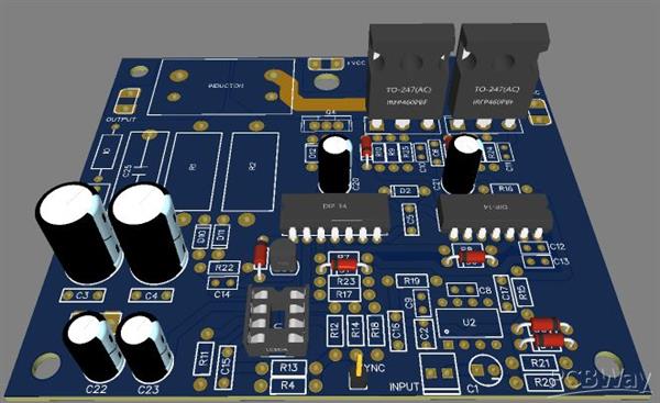
500W UCD Class D Amplifier
Hi guys, my name is Maria and I am a student of electronic engineering at the pedagogical and technological university of Colombia, today I want to present a UCD amplifier, but this time only with N channel mosfets, scalable from 500Wrms to 1250Wrms) This time We are taking advantage of the fact that at least, here in Colombia, the IR2110 is being obtained at a good price and of a very decent quality, and that makes it possible not to go crazy with discrete mosfet drivers, and to use only N-channel mosfets ... And by the way, the amp goes at one!

Let's clarify that this is a proof of concept in which many of the desirable characteristics in high power amplifiers have been omitted, such as protections and fuses that will be left to the reader.
The main objective of this project is to bring a Class D amplifier closer to those who have no experience with this type of circuitry and one of the most important rules in its design was to simplify it as much as possible and use only common components, low cost and easy to get for everyone.
It is also an exercise for the reader, with what to feed this little monster, if they really want to reach its maximum power since it can deliver up to 1200W, an idea could be to use a toroidal transformer since they have a good performance and of course a generous amount of capacitors if you really want to get full power

I have specified IRFP260 as mosfets ... They are not the only possible ones ... For lower powers, much cheaper N-channel mosfets could be used. For example, if the supply voltage will never exceed +/- 20 volts, you could use the IRFZ44, or for 200Wrms over 4/8 ohms, the IRF640 ... Simply, smaller mosfets will heat more.
In relation to the heatsink, really, you have to put it ... And the reason is very simple: Although this amplifier has a theoretical efficiency of 97%, at 1250Wrms, that implies 37W of dissipation in the mosfets, so they require a heatsink.
However, for example, for 200Wrms output, the power dissipated in the mosfets will be 6W in each one, so a few simple clips could work well. Simply, place an aluminum foil as a heatsink ... And remember that this time, both mosfets have to be isolated from the heatsink with micas and insulating washers ... But the MJE MUST NOT be isolated, because that transistor puts the heatsink to ground to suppress noise emission.

The last issue I have left to name is the output inductor issue: It must be able to withstand the peak output current of the amplifier without saturating or burning out. Personally, I use 1mm² of section for every 4 ampere of current (that is, for 8A, I use a wire with 2mm² of section) ... Preferably, instead of using a single wire, use 2 or 3 in parallel whose section added give the required wire section. This will improve the performance of the inductor (I would use, to obtain an equivalent section of 2mm², 3 wires of 0.66mm² section put in parallel)

I personally recommend buying the inductors directly since if you do not have experience making them it can become a headache, also this type of amplifier needs that especially the inductor be of the best quality and of a specific frequency since the quality of the sound that we will get from the amplifier, it is for these reasons that I decided to use the inductor 744013119220.
I thank the PCBWay company for the support received to carry out this great project
- Comments(5)
- Likes(5)


