


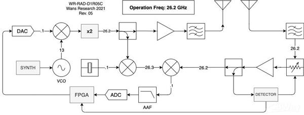
26GHz Automotive FMCW Radar

The D1R05C FMCW Automotive Radar utilizes the Ka-band (26GHz) for detecting Doppler frequency shifts and phase offsets in FM ramps to sense the speed and range of an object in aperture. This antenna-on-package board boasts a robust architecture, including automatic gain control and superheterodyne receiver, all in a miniaturized form factor (6cm x 6cm).
Key Features Overview:
- 27.5 dBm peak output power
- 80 m/s top detection speed
- Weather and fog resilience
- Low phase noise and jitter
- Minimized spectral thermal floor
- Non-zero IF baseband
- SPI-compatible interface
By using the Ka-band against the typical E-band for automotive applications, this radar provides readings even in foggy or non-nominal weather conditions. Phase locking allows for low phase jitter and noise, meaning more accurate range detection. Non-zero IF baseband allows for better spectral characteristics and ease of use for DSP. The usage of discrete elements atop the board is to aid in reduced cost. In addition to the aforementioned, isolation barriers, isolative directional coupling, and MS-CPW bordering transitions help to reduce spectral noise and thus increase performance reliability.
I was inspired to make this project to address the need for reliable radar under abnormal weather conditions and a wide thermal range, all whilst keeping a small and manageable form factor for use in automotive and robotics applications. A second, unfinished board will include the low-noise power supplies, FPGA for DSP, and ADC/DAC's. It will also support SPI communication for implementation into almost any system without having to account for the hiccups with I2C systems. To me, this project was a testament to both my analog and digital skills, proving quite a challenge.
Because a board of this magnitude can be quite expensive, the entire board (in parts and whole) have been tested using various 2.5D and 3D simulators, including CST, Microwave Office, and Sonnet Suite.
Fabrication Requirements:
- Rogers 4350B Substrate
- 0.254 Substrate Thickness/height
- ENIG finish
- Impedance Control
- 0.1mm track/trace spacing
- Front and back SMD assembly
- Abide strictly to the documented reflow soldering profile
As a high school student, I have no funding available to manufacture and fabricate this board. Sponsorship is greatly appreciated.
This board is Copyrighted (C) by Ryan Wans under "Wans Research" 2021. Contact ryan@ryanwans.com for more info.
Apply for sponsorship >>- Comments(1)
- Likes(6)


