

|
FreeCad |
|

|
KiCADKicad
|
|
|
|
Microsoft Excel |
DC Vibration Motor
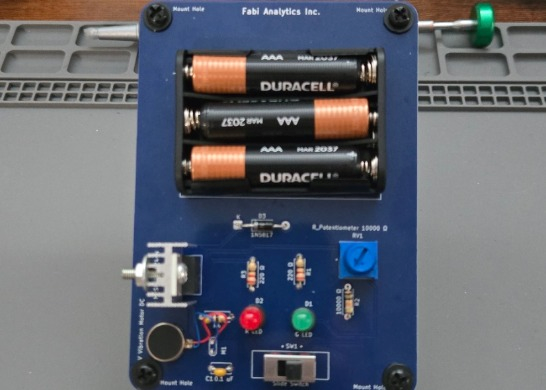
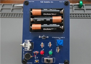
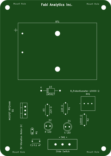
There are numerous things the vibration motor is used for, such as video game controllers, smartphones, testing frequency, and massage guns. This is a basic vibration motor circuit for educational and hobbyist purposes. It comes with a list of the required parts and tools, along with a datasheet for theory/circuit analysis.
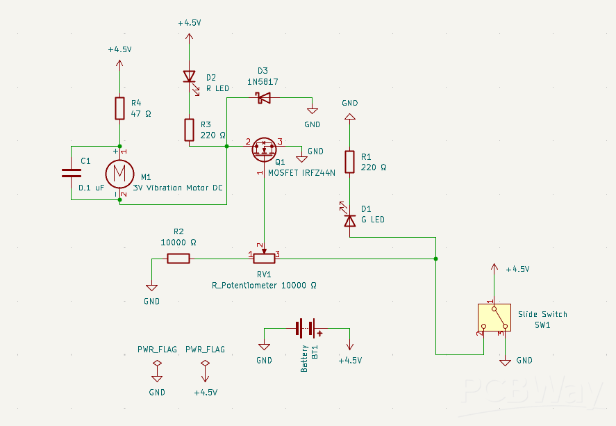
Note on red LED Behavior: The red LED (D2) illuminates when the vibration motor (M1) is subjected to external mechanical vibration, provided the slide switch (SW1) is switched on. This occurs because mechanical vibration generates back-EMF across the parallel motor branch, driving current through the red LED even when the potentiometer (RV1) is turned down. As well, Individual test results may vary slightly due to component tolerances and variations in motor resistance across other parts of the circuit. These minor differences are expected and will not impact the overall operation of the circuit.
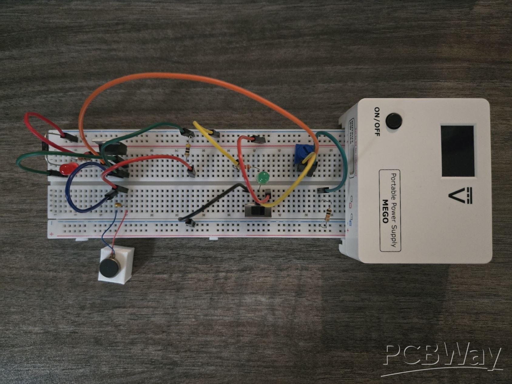
Breadboard/Prototype Instructions:
1. Connect the third pin of the potentiometer to Ground with a 10 kΩ resistor.
2. Attach the first pin of the potentiometer to the 2nd pin of the slide switch.
3. Place the green LED and the 220 Ω resistor in series with the 2nd pin of the switch and Ground.
4. Connect the 3rd pin of the switch to Ground.
5. Connect the 1st pin of the switch to the Positive rail.
6. Test the switch to make sure the green LED turns on.
7. Once you’ve completed the green LED sub-circuit, connect the 2nd pin of the potentiometer to the Gate pin of the MOSFET. This is what’ll gradually activate the vibration motor when the resistance drops. When the Gate threshold voltage reaches anywhere between 2 and 4 volts, the Drain pin will draw current to the red LED and the vibration motor. The lower the resistance of the potentiometer, the higher the Gate voltage.
8. Place the other 220 Ω resistor in series with the red LED between the Positive rail and the Drain pin of the MOSFET.
9. Attach the blue wire of the motor to the Drain pin of the MOSFET, and attach the red wire in series with the 47 Ω resistor to the Positive rail.
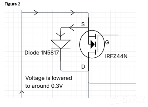
10. Connect the 1N5817 Diode across the MOSFET (Drain to Source). The anode connects to Ground, and the cathode connects to the Drain pin. This diode acts as a protective snubber for the MOSFET. Under normal operation (Figure 1), the diode is reverse-biased and blocks current. However, when the motor switches off and creates a voltage spike (Figure 2), the diode becomes forward-biased, clamping the inductive kickback to around 0.3V and safely routing the current away from the switch.
11. Attach the aluminum heatsink to the MOSFET with the screw, nut, and washer. Over time, the MOSFET can get hot, whereas the heatsink will help dissipate the heat. Once you attach the heatsink to the MOSFET, make it snug.
12. Insert the capacitor in parallel with the vibration motor to suppress any EMI and electrical noise.
13. Turn the power supply on and make sure it’s set at 4.5V.
14. Flip the slide switch to turn the green LED on.
15. Slowly rotate the potentiometer to gradually increase the brightness of the red LED and the vibration of the motor.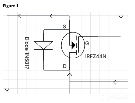
DC Vibration Motor
Project images are for reference only. Actual production is based on the manufacturing files on the project page.
Please review the designer's notes (e.g., PCB thickness) and select the appropriate options.
PCBWay is not responsible
for issues caused by unsuitable parameter selections.
For more important ordering information, please refer to
Read More









Raspberry Pi 5 7 Inch Touch Screen IPS 1024x600 HD LCD HDMI-compatible Display for RPI 4B 3B+ OPI 5 AIDA64 PC Secondary Screen(Without Speaker)
BUY NOW


- Comments(0)
- Likes(0)
More by Preston Fabbi
-
Programmable Mist Maker - XIAO / QT PY Extension
2334 2 2 -
RadioHAT - Raspberry Pi radio development platform
2022 0 4 -
-
-
-
ARPS-2 – Arduino-Compatible Robot Project Shield for Arduino UNO
4181 0 6 -
A Compact Charging Breakout Board For Waveshare ESP32-C3
4945 3 8 -
AI-driven LoRa & LLM-enabled Kiosk & Food Delivery System
5723 2 2 -