|
|
ESP32 arduino nanoESP32 arduino nano
|
x 1 | |
|
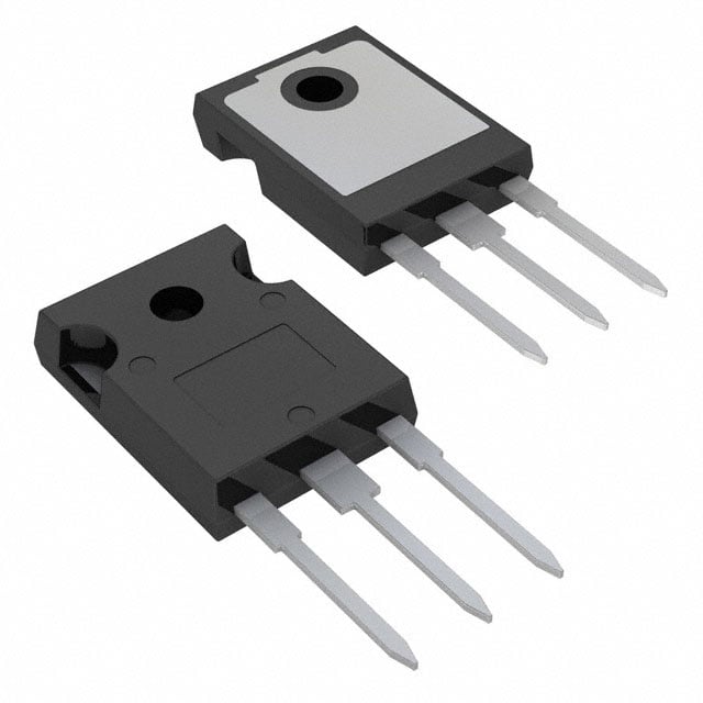
IRFP054NPBFInfineon Technologies
|
x 1 | |
|
|
Generic 12V JackVarious
|
x 1 | |
|
|
CustomCustom/3D-print
|
x 1 | |
|
|
buck converter |
x 1 |

|
Fusion 360Autodesk
|
|

|
arduino IDEArduino
|
|

|
PrusaslicerPrusa
|
The Rainbowz
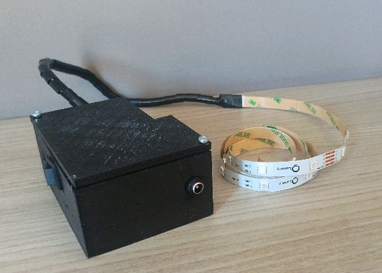
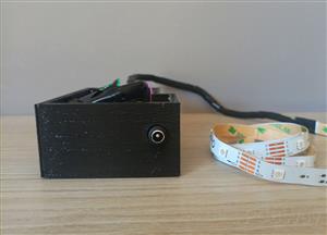
The RainbowZ is a small box which can be used to control any 12V RGB led strip with your phone using an arduino esp32 and its bluetooth function. The idea of the project comes from a necessity: the led strip controller that I was using required an internet connection to work properly, which was kind of a problem because my wifi rooter was far away from the location where the led strip was installed, so I decided to make my own controller that work without wifi. Initially, I thought about making it using an IR sensor that caught specific signal from a smartphone that was then processed by the arduino, but after some tries, I realised that using the bluetooth signal was much easier and more practical because the bluetooth function was already implemented in the arduino esp32 and than every smartphone would be able to control it from longer distances without any problem.
HOW TO USE IT
The RainbowZ is controlled by an app created with “MIT app inventor”. This app displays a total of 15 colors. Every color has its own button and when one is pressed, the arduino receives a specific string via bluetooth that turns on the led strip on the right color.
In this part of the code, for example, the result is the string that the arduino receives via bluetooth, so if the result is 2, the led strip will display the colour pink (255,0,255) using an analogwrite:
if (result == '2') { int colore_personal[3] = {255,0,255}; analogWrite(pinR, colore_personal[0]); analogWrite(pinB, colore_personal[1]); analogWrite(pinG, colore_personal[2]); } else if (result == '3') { int colore_personal[3] = {252,186,3}; analogWrite(pinR, colore_personal[0]); analogWrite(pinB, colore_personal[1]); analogWrite(pinG, colore_personal[2]); }
There are also 4 buttons for the fade effect which create a smooth transaction from similar color. To do this effect, I made a function called “fadetoColor” , which allows a transaction between 2 color:
void fadeToColor(byte target[3], int stepDelay) { if (millis() - lastFadeTime < stepDelay) return; lastFadeTime = millis(); bool finished = true; for (int i = 0; i < 3; i++) { if (colorNow[i] < target[i]) { colorNow[i]++; finished = false; } else if (colorNow[i] > target[i]) { colorNow[i]--; finished = false; } } analogWrite(pinR, colorNow[0]); analogWrite(pinG, colorNow[1]); analogWrite(pinB, colorNow[2]); if (finished) { ColorInd = (ColorInd + 1) % numColors; } }
First, it receives two pieces of information: the target (the final color) and the stepdelay, which is the speed of the fade. Then, it controls the three colours of the strip (RGB) changing the i variable from 0 to 3 and after it increases the current color if the target is major or it decreases it if it is minor until it reaches the target.
To control how many times the color changes, at the start of the function it subtracts the “lastfadetime” to millis obtaining how much time passed since the last change. If it is minor than the stepdelay it continues to wait until it becomes major to continue the Fade.
When the color reaches the target color, the bool “finished” becomes “true” and passes to the next color increasing “colorInd”, which is the number of the color in an array.
“numColors” is the size of the array.
To activate “FadeToColor”, I use four boolean variables, calling them FadeActive1, FadeActive2 etc., one per color section. When the arduino receives a specific string, one of the FadeAttivo goes from “false” to “true”:
if (result == 'H') { FadeActive3 = !FadeActive3; FadeActive2 = false; FadeActive1 = false; Fadeactive = false; } if (result == 'G') { FadeActive2 = !FadeActive2; FadeActive3 = false; FadeActive1 = false; Fadeactive = false; }
when this append, an “if” functionality starts “fadeToColor”:
if (fadeActive) { fadeToColor(colorsFade[ColorInd], m); } if (fadeActive1) { fadeToColor(colorsFade1[ColorInd], m); } if (fadeActive2) { fadeToColor(colorsFade2[ColorInd], m); } if (fadeActive3) { fadeToColor(colorsFade3[ColorInd], m); }
The targets become “colorsFade”, which are four arrays containing all the color we want in the Fade; and the stepdelay becomes “m”, that can be later changed to regulate the speed using 2 buttons on the app.
These is an example of the arrays, declared at the start of the code:
byte coloriFade3[][3] = { {255, 180, 210}, {255, 70, 150}, {255, 0, 120}, {200, 0, 180}, {140, 0, 255}, {80, 0, 200}, {40, 0, 120}, {120, 20, 180}, {220, 50, 170}, {255, 120, 190}, {255, 180, 210} };
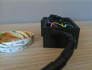
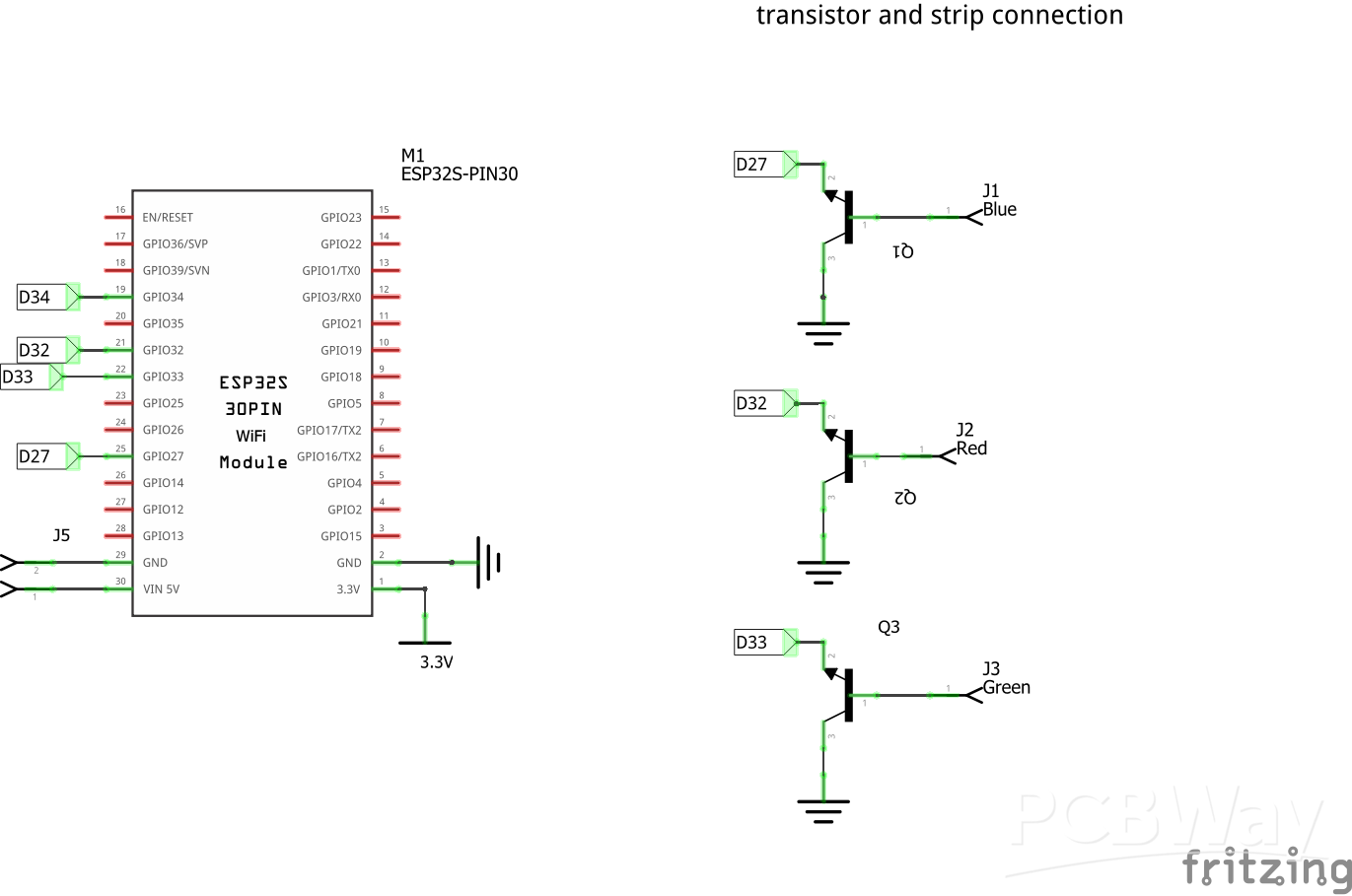
The RainbowZ is powered by a 12V power supply, which gives the strip the necessary voltage to work properly. A buck converter then lowers the voltage to ≃4V to power the arduino. 3 arduino's pins control the three RGB pins of the led strip using transistors. The circuit is closed in a small box designed with fusion 360 and then 3d printed.
HOW TO ASSEMBLY IT
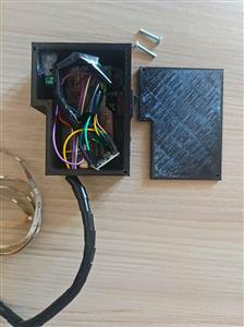
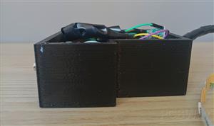
There are two pieces that I used to make the box: the box and its top.
First, you have to put the pcb or the breadboard where you assembled the esp32 and the buck converter inside the box. Then, there are three main holes: The frist one is where you are going to glue the 12V pin; the second one is for a small on-off button to control the ground before connecting it to the pcb to have a simple way to turn on and off the RainbowZ, and then the third one is an exit for the led strip. Once you have finished to put all the things together, you can easily screw the top to the box
The Rainbowz
Project images are for reference only. Actual production is based on the manufacturing files on the project page.
Please review the designer's notes (e.g., PCB thickness) and select the appropriate options.
PCBWay is not responsible
for issues caused by unsuitable parameter selections.
For more important ordering information, please refer to
Read More


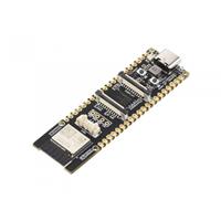
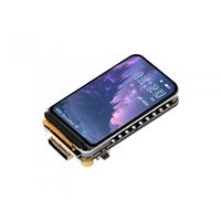
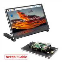
Raspberry Pi 5 7 Inch Touch Screen IPS 1024x600 HD LCD HDMI-compatible Display for RPI 4B 3B+ OPI 5 AIDA64 PC Secondary Screen(Without Speaker)
BUY NOW


- Comments(0)
- Likes(0)
More by Paolo Graziuso
-
-
-
-
-
-
-
AudioLink – USB & Bluetooth LE Audio / Auracast Receiver with Balanced Line Outputs (nRF5340)
491 0 1 -
-
-
-
Émetteur Récepteur Optique Expérimental (communication UART ATtiny + fibre optique)
477 0 1