

|
|
Mini Breadboard |
x 2 | |
|
|
Arduino Nano |
x 1 | |
|
|
MPU6050 |
x 1 | |
|
|
L293d driver IC |
x 1 | |
|
|
N20 gear motor |
x 2 | |
|
|
N20 motor brackets |
x 2 | |
|
|
N20 motor wheels |
x 1 |

|
arduino IDEArduino
|
|

|
Autodesk Fusion 360Autodesk
|
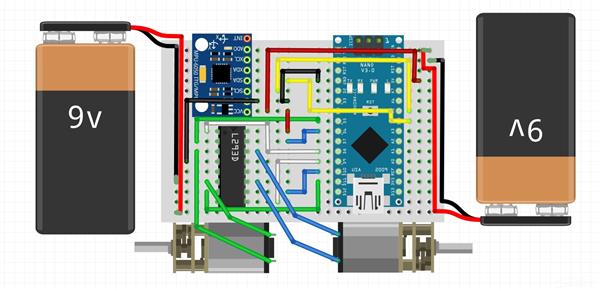
The Breadboarded Self Balancing Robot
A self Balancing Robot where electronic modules and components are connected to each other on a breadboard.
How easy it is to assemble:
- 3D print the chassis
- mount the brackets on the chassis
- insert the motor
- connect all modules and components together on breadboard using jumpers
- insert the breadboard and batteries on the chassis
Making the Robot to balance:
- install the drivers for arduino
- install libraries for MPU6050 and PID controller
- Upload the code in arduino
Power the robot using 9V batteries and see it in action
More build details here.
All the project files are on Github.
//Installing necessary libraries
#include <Wire.h>
#include <I2Cdev.h>
#include <MPU6050.h>
#include <PID_v1.h>

//defined macros
#define LeftMotorDir 11
#define LeftMotorPower 5
#define RightMotorDir 10
#define RightMotorPower 6

#define LeftMotorEnable 8
#define RightMotorEnable 9

//the angle where the robot is stable
double Setpoint = -0.75;

double Input, Output;

//PID controllers
double Kp = 4.6;
double Kd = 0.04;
double Ki = 1;

//required variables
int accY, accZ, gyroX;
float accAngle = 0, gyroAngle = 0, previousAngle = 0;
float gyroRate = 0;
int val = 0;

//instance of class PID
PID myPID(&Input, &Output, &Setpoint, Kp, Ki, Kd, DIRECT);

//instance of class MPU6050
MPU6050 mpu;

/*.............................SETUP.................................*/
/*...................................................................*/

void setup() {

  //initializing MPU6050
  mpu.initialize();

  //setting the pinmodes
  pinMode(LeftMotorEnable, OUTPUT);
  pinMode(LeftMotorDir, OUTPUT);
  pinMode(LeftMotorPower, OUTPUT);

  pinMode(RightMotorEnable, OUTPUT);
  pinMode(RightMotorDir, OUTPUT);
  pinMode(RightMotorPower, OUTPUT);

  //making enable pin high
  digitalWrite(LeftMotorEnable, HIGH);
  digitalWrite(RightMotorEnable, HIGH);

  //setting PID parameters
  myPID.SetMode(AUTOMATIC);
  myPID.SetOutputLimits(-255, 255); // may change (50,255);
  myPID.SetSampleTime(5); //how often pid is evaluated in millisec
  myPID.SetControllerDirection(REVERSE);

  //initialize the timer
  initTimer2();

}

/*..............................LOOP.................................*/
/*...................................................................*/

void loop() {

  accZ = mpu.getAccelerationZ();
  accY = mpu.getAccelerationY();

  gyroX = mpu.getRotationX();

  accAngle = atan2(accZ, -accY) * RAD_TO_DEG;

  gyroRate = gyroX / 131;

  Input = 0.97 * (previousAngle + gyroAngle) + 0.03 * (accAngle);
  previousAngle = Input;

  myPID.Compute();

  if (Output > Setpoint)
  {
    digitalWrite(LeftMotorDir, LOW);
    digitalWrite(RightMotorDir, LOW);
    val = map(Output, 0, 255, 18, 255);
    analogWrite(LeftMotorPower, val);
    analogWrite(RightMotorPower, val);
  }

  if (Output < Setpoint)
  {
    digitalWrite(LeftMotorDir, HIGH);
    digitalWrite(RightMotorDir, HIGH);
    val = map(Output, -255, 0, 0, 237);
    analogWrite(LeftMotorPower, val);
    analogWrite(RightMotorPower, val);
  }
}


/*................... ........ISR_TIMER2.............................*/
/*...................................................................*/

ISR(TIMER2_COMPA_vect)
{
  gyroAngle = (float)gyroRate * 0.001;
}

/*...........................iniTimer2...............................*/
/*...................................................................*/

void initTimer2()
{
  //reset timer2 control register A
  TCCR2A = 0;

  //set CTC mode
  TCCR2A |= (1 << WGM21);
  TCCR2A &= ~(1 << WGM20);
  TCCR2B &= ~(1 << WGM22);

  //prescaler of 128
  TCCR2B &= ~(1 << CS21);
  TCCR2B |= ((1 << CS22) | (1 << CS20));

  //reset counter
  TCNT2 = 0;

  //set compare register
  OCR2A = 125;

  //enable timer1 compare match interrupt
  TIMSK2 |= (1 << OCIE2A);

  //enable global interrupt
  sei();
}
The Breadboarded Self Balancing Robot
Project images are for reference only. Actual production is based on the manufacturing files on the project page.
Please review the designer's notes (e.g., PCB thickness) and select the appropriate options.
PCBWay is not responsible
for issues caused by unsuitable parameter selections.
For more important ordering information, please refer to
Read More









Raspberry Pi 5 7 Inch Touch Screen IPS 1024x600 HD LCD HDMI-compatible Display for RPI 4B 3B+ OPI 5 AIDA64 PC Secondary Screen(Without Speaker)
BUY NOW


- Comments(0)
- Likes(1)
- 1 USER VOTES
- YOUR VOTE 0.00 0.00
-
10design
-
10usability
-
10creativity
-
10content
More by Aditya ATOM

-
Programmable Mist Maker - XIAO / QT PY Extension
2333 2 2 -
RadioHAT - Raspberry Pi radio development platform
2021 0 4 -
-
-
-
ARPS-2 – Arduino-Compatible Robot Project Shield for Arduino UNO
4180 0 6 -
A Compact Charging Breakout Board For Waveshare ESP32-C3
4943 3 8 -
AI-driven LoRa & LLM-enabled Kiosk & Food Delivery System
5722 2 2 -