
|
KiCad 9.0 |
Smart Chessboard with Hall-Effect Piece Detection and RGB LEDs
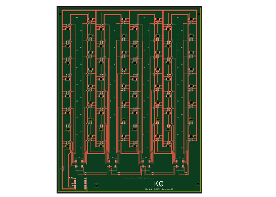
This smart chessboard detects every piece with 64 Hall-effect sensors and lights each square from below with an addressable RGB LED. Everything sits on one single-layer PCB that is also the playing surface. The design (v1.0) is finished in KiCad. I am asking PCBWay to manufacture the board so I can build and test the first working prototype.
KEY SPECIFICATIONS
- Board size: 212 x 275 mm, FR-4, 1.6 mm
- Copper: 1 layer (all routing on one side, zero vias)
- Playing field: 8 x 8 squares, 25 mm pitch (200 x 200 mm)
- Controller: Seeed Studio XIAO ESP32-C3 (Wi-Fi + Bluetooth LE)
- Piece detection: 64 Hall switches, SOT-23, open-drain
- Inputs: 4 x MCP23017 I2C port expanders (addresses 0x20-0x23)
- Lighting: 64 x SK6812MINI-E reverse-mount RGB LEDs in one data chain
- Power: 5 V over USB-C, Schottky-protected LED/sensor rail
- Parts per board: 268 SMD parts, all hand-solderable (1206, SOT-23, SOIC-28, SMA)
1. PROJECT BACKGROUND
I am a second-year student of Electronics and Technical Computer Science at TGM in Vienna, Austria. I started this project to build a complete product myself, from schematic to PCB layout to firmware, instead of only working with breadboards and modules.
A chessboard is a good challenge for this. It needs 64 sensor inputs, 64 individually controlled lights, a microcontroller with wireless connectivity, and a large PCB that has to look good, because the board itself is the product.
Commercial electronic chessboards cost several hundred euros, and many need special pieces with built-in chips. My goals are:
- Normal pieces: each piece only needs a small magnet in its base.
- Guidance by light: the board shows legal moves, the last move, check, and the opponent's move from an online game.
- Low cost and easy to build: one PCB, hand-solderable parts, no special tools.
- Learning: practise KiCad, I2C, addressable LEDs and ESP32 firmware on a real project, and document it so others can rebuild it.
2. SYSTEM ARCHITECTURE
The system has three blocks that share one 5 V supply: the controller, the sensor matrix and the LED chain. The controller reads all sensors over I2C and drives all LEDs over a single data wire.
- XIAO ESP32-C3: pins D10 (SCL) and D7 (SDA) go to the four MCP23017 expanders, with 4.7k pull-ups to 3.3 V. Pin D1 drives the LED data chain.
- 4 x MCP23017: each reads 16 Hall sensors (two files of the board).
- 64 LEDs: one chain in a serpentine pattern, A1 to A8, then B8 to B1, then C1 to C8, and so on.
- Power: 5 V goes through an SS14 Schottky diode to the VLED rail (about 4.6 V), which feeds all LEDs and Hall sensors. The XIAO's 3.3 V output feeds the expanders and the I2C pull-ups.
Main components:
- 1 x Seeed Studio XIAO ESP32-C3 (castellated module, soldered flat)
- 4 x MCP23017-E/SO port expander (SOIC-28 wide)
- 64 x Hall switch, open-drain, e.g. TI DRV5023 (SOT-23)
- 64 x SK6812MINI-E RGB LED (reverse mount through a board cut-out)
- 68 x 100 nF X7R decoupling capacitor (1206)
- 64 x 0 ohm jumper (1206)
- 2 x 4.7 kohm I2C pull-up (1206)
- 1 x SS14 Schottky diode (SMA)
- 4 x M3 mounting holes (3.2 mm)
How the modules work together:
1. A player lifts a piece. The magnet leaves the Hall switch under that square, and its output goes from low to high.
2. The ESP32-C3 polls the four expanders over I2C. Eight bytes describe the whole board, one bit per square.
3. The firmware compares the new board state with the old one and works out the move.
4. The ESP32-C3 sends new colours down the LED chain, for example to light the legal target squares of the lifted piece.
5. Over Wi-Fi, the board can later send moves to an online game and show the opponent's reply with the LEDs.
3. DESIGN APPROACH
The PCB is the playing surface
All parts sit on the underside of the board. The top side has no copper and no components, so it is completely smooth. This is the side you play on.
Each square has a 3.7 x 3.2 mm cut-out. The SK6812MINI-E is a reverse-mount LED: its body sits in the cut-out and its legs are soldered to pads on the underside. The light shines up through the board, so a thin printed or laminated chessboard overlay on top lights up from below.
Why one copper layer
I routed the whole board on one copper layer with zero vias (1,437 track segments). This keeps the top surface flat. Where a trace has to cross another net, a 0 ohm 1206 resistor bridges over it. Each square has one bridge, which feeds that square's Hall sensor from the LED supply. Track widths are 0.3 mm for signals and 1.2-2.0 mm for the 5 V and GND rails.
Sensors
Each square has one SOT-23 Hall switch (DRV5023 class) with an open-drain output. When a magnet is near, the output pulls low. Otherwise the MCP23017's internal pull-up pulls it to 3.3 V. So the sensor can run on the 4.6 V rail, but the signal never goes above 3.3 V at the expander. A switch with a fixed threshold gives a clean digital signal, so no ADC or calibration is needed.
The four MCP23017s use the I2C addresses 0x20-0x23, set with pins A0-A2. Each one reads two files: IC1 reads A and B, IC2 reads C and D, IC3 reads E and F, IC4 reads G and H. The RESET pins are tied high. The interrupt pins are not used in v1.0, because polling 8 bytes at 400 kHz takes well under 1 ms.
LEDs
The 64 LEDs form one daisy chain in a serpentine pattern. This keeps every data connection to one short trace between neighbouring squares. Each LED has its own 100 nF capacitor directly at its supply pins.
Power and the Schottky diode trick
The board runs on 5 V from the XIAO's USB-C port. The SS14 Schottky diode between 5 V and the LED/sensor rail has two jobs:
- It protects the USB port against back-feeding.
- It lowers the LED supply to about 4.6 V. The SK6812 needs a data-high level of about 0.7 x VDD. At 5 V that is 3.5 V, which is more than the ESP32-C3's 3.3 V output. At 4.6 V it is about 3.2 V, so the 3.3 V signal works without a level shifter.
The firmware limits LED brightness so the total current stays within what a USB port can supply. In normal play only a few squares are lit at once.
Controller
The XIAO ESP32-C3 is soldered flat with its castellated pads, so there are no headers and the board stays thin. It brings Wi-Fi, Bluetooth LE, USB-C programming and a 3.3 V regulator in a 21 x 17.5 mm module. Only three GPIOs are used: D1 for LED data, D7 for SDA and D10 for SCL. The other pins stay free for future features such as a buzzer or buttons.
4. DEVELOPMENT PROGRESS
The hardware design is complete (revision 1.0). The next step is a manufactured board.
Completed:
- Concept, part selection and power budget
- Custom KiCad symbol and footprint library (reverse-mount LED with board cut-out, XIAO SMD, SOIC-28, SOT-23, 1206, SMA)
- Full schematic: 64 squares, 4 port expanders, controller and power
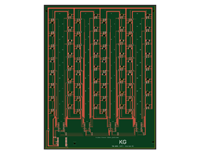
- Single-layer PCB layout, 212 x 275 mm, routed with zero vias
- Silkscreen with square names (A1-H8), logo and version
- Bill of materials and Gerber/drill export
Next steps and testing plan:
1. Visual check and continuity: inspect the bare boards and measure 5 V, VLED, 3V3 and GND against each other for shorts before fitting parts.
2. Staged assembly: solder the XIAO, the diode and one MCP23017 first, check the 3.3 V rail and run an I2C scan. All four addresses must answer once all expanders are fitted.
3. LED chain test: fit the LEDs file by file and run a test pattern after each file, so a faulty LED is easy to find.
4. Sensor test: move a magnet over every square and log the 64-bit board state over USB serial. Every square must switch, and none may stay stuck.
5. Magnet tuning: test magnet sizes and overlay thickness so a piece triggers only its own square.
6. Power measurement: measure the current with different LED patterns and set a safe brightness limit for USB power.
7. Firmware: board-state and move detection, legal-move highlighting, then a Wi-Fi connection to an online chess platform.
8. Enclosure: a 3D-printed or wooden frame using the four M3 holes, plus a printed overlay for the playing surface.
5. MANUFACTURING REQUIREMENTS
I am asking PCBWay to manufacture 5 bare PCBs of the main board. I will assemble them myself by hand.
- Quantity: 5 pcs
- Dimensions: 212 x 275 mm, rectangular
- Layers: 1 (single-sided copper)
- Material / thickness: FR-4, 1.6 mm
- Copper weight: 1 oz
- Min. track / spacing: 0.3 mm / 0.2 mm
- Vias: none
- Holes: 4 x 3.2 mm NPTH (M3 mounting)
- Internal cut-outs: 64 x 3.7 x 3.2 mm milled slots (one per LED)
- Solder mask: both sides (black would suit the playing side best)
- Silkscreen: white, component side
- Surface finish: HASL lead-free or ENIG
- Optional: SMT stencil for the component side
Note on the cut-outs: the 64 LED openings are internal milled cut-outs on the Edge.Cuts layer. Small rounded corners from the milling bit are fine, because the LED body is smaller than the opening.
How the boards will be used:
- Board 1: first prototype for bring-up and all tests from section 4.
- Board 2: the finished chessboard in its case.
- Boards 3-5: spares for assembly mistakes, and boards for friends who want to rebuild the project.
If the tests show that changes are needed, I will document them and publish a revision 1.1.
6. PROMOTION AND ACKNOWLEDGEMENT
If PCBWay sponsors the boards, I will do the following as soon as the bare boards arrive:
- PCBWay project page: an update with photos of the bare boards and a short review of the manufacturing quality.
- Instagram: a short story unboxing the boards, tagging PCBWay.
- GitHub: the KiCad files in a public repository, with a note about PCBWay in the README.
7. ABOUT THE AUTHOR
I am Kartik Ghotra, a student at TGM (Hoehere Technische Bundeslehranstalt) in Vienna, studying Electronics and Technical Computer Science. I enjoy designing my own electronics projects, repairing and analysing electronic devices, and building PCs. For this project I use KiCad, C on microcontrollers, soldering and 3D printing.
Thank you to PCBWay for considering this project. I look forward to sharing the build with the community.
Smart Chessboard with Hall-Effect Piece Detection and RGB LEDs
Project images are for reference only. Actual production is based on the manufacturing files on the project page.
Please review the designer's notes (e.g., PCB thickness) and select the appropriate options.
PCBWay is not responsible
for issues caused by unsuitable parameter selections.
For more important ordering information, please refer to
Read More


Raspberry Pi 5 7 Inch Touch Screen IPS 1024x600 HD LCD HDMI-compatible Display for RPI 4B 3B+ OPI 5 AIDA64 PC Secondary Screen(Without Speaker)
BUY NOW


- Comments(0)
- Likes(0)
 More by Engineer
-
-
-
-
-
-
-
AudioLink – USB & Bluetooth LE Audio / Auracast Receiver with Balanced Line Outputs (nRF5340)
463 0 1 -
-
-
-
Émetteur Récepteur Optique Expérimental (communication UART ATtiny + fibre optique)
460 0 1