
|
Arduino nanoArduino
|
|

|
arduino IDEArduino
|
Simple H-Bridge
🔋 Arduino Nano 50 Hz SPWM H-Bridge Driver
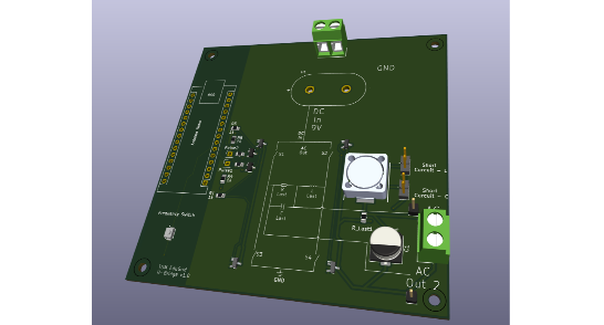
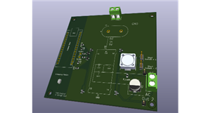
This project uses an Arduino Nano to generate 50 Hz sinusoidal PWM (SPWM) signals for driving a simple H-bridge inverter. It produces two complementary PWM outputs on pins D5 and D6, suitable for MOSFET or IGBT gate drivers (e.g. IR2104, IR2110).
A push-button on D3 toggles the PWM carrier frequency between ≈977 Hz and ≈244 Hz, allowing quick testing of different switching speeds. The sine waveform is created from a 128-point lookup table, updated by a Timer2 interrupt, while Timer0 handles high-speed PWM generation.
✨ Features
50 Hz sinusoidal PWM output
Complementary outputs (D5 & D6) for H-bridge control
Switch-selectable carrier frequency (977 Hz / 244 Hz)
Hardware-based timing for stable, low-jitter waveform
Compatible with standard Arduino Nano boards
⚙️ Technical Info
ParameterValuePWM PinsD5 (OC0B) & D6 (OC0A)Control InputD3 (toggle switch, pull-up enabled)Sine Frequency50 Hz (fixed)Table Size128 samplesSupply Voltage5 V (Arduino logic)
🔌 Applications
Small inverter or UPS prototypes
SPWM learning and testing
AC waveform or motor control experiments
Simple, reliable, and educational — this project demonstrates how to generate clean sinusoidal PWM using the Arduino’s built-in timers for real H-bridge control.
/*
  Arduino Nano - 50 Hz Sinusoidal PWM (SPWM) on D5 & D6
  This code generates two complementary PWM signals with dead time.
  A switch on D3 toggles the carrier frequency between two states.

  - Carrier PWM Frequencies (Fast PWM Mode):
    - State 1: ~977 Hz (Prescaler 64)
    - State 2: ~244 Hz (Prescaler 256)
  - Sine Wave Frequency: ~50.08 Hz (constant)
  - Output: Complementary SPWM on D5 & D6.
*/

#include <Arduino.h>

// Define the pin for the toggle switch.
#define SWITCH_PIN 3

// A larger table size gives a smoother sine wave.
#define SINE_TABLE_SIZE 128
// Defines the dead time. Not needed because of the natural deadtime with R3 and R1
#define DEAD_TIME 0

// Array to store pre-calculated sine wave duty cycle values.
byte sine_table[SINE_TABLE_SIZE];

// Volatile variable for the current position in the sine table.
volatile int table_index = 0;

// --- MODIFICATION: State variables for the toggle logic ---
// Tracks whether we are in high or low frequency mode.
volatile bool useHighFrequency = true;
// Stores the last-read state of the button to detect a press.
int lastButtonState = HIGH;

void setup() {
  // --- Step 1: Pre-calculate the sine lookup table ---
  for (int i = 0; i < SINE_TABLE_SIZE; i++) {
    // Calculate a sine wave value, scale it from -1..1 to 0..255
    float val = sin(i * 2.0 * PI / SINE_TABLE_SIZE);
    sine_table[i] = (byte)((val + 1.0) * 127.5);
  }

  // --- Step 2: Configure the switch pin ---
  // Set D3 as an input with an internal pull-up resistor.
  pinMode(SWITCH_PIN, INPUT_PULLUP);
  // Read the initial state of the button.
  lastButtonState = digitalRead(SWITCH_PIN);

  // --- Step 3: Configure Timer0 for complementary PWM carrier ---
  pinMode(6, OUTPUT); // D6 = OC0A
  pinMode(5, OUTPUT); // D5 = OC0B

  TCCR0A = 0; // Clear control registers
  TCCR0B = 0;

  // --- MODIFICATION: Set Fast PWM mode for more frequency options ---
  // Mode 3: Fast PWM, TOP = 0xFF (255)
  TCCR0A |= (1 << WGM01) | (1 << WGM00);

  // Configure complementary (inverted) outputs on OC0A and OC0B.
  TCCR0A |= (1 << COM0A1) | (1 << COM0B1) | (1 << COM0B0);

  // --- MODIFICATION: Set initial prescaler for ~977 Hz ---
  // Freq = 16,000,000 / (64 * 256) = 976.56 Hz
  TCCR0B |= (1 << CS01) | (1 << CS00); // Prescaler 64

  // --- Step 4: Configure Timer2 to generate the 50 Hz update interrupt ---
  // This part is unchanged.
  TCCR2A = 0; // Clear control registers
  TCCR2B = 0;

  TCCR2A |= (1 << WGM21); // Set CTC Mode
  TCCR2B |= (1 << CS22);  // Set prescaler to 64

  // OCR2A = (16,000,000 / (64 * 50Hz * 128 steps)) - 1 = 38
  OCR2A = 38;

  // Enable Timer2 Compare Match A Interrupt.
  TIMSK2 |= (1 << OCIE2A);

  // Enable global interrupts.
  sei();
}

// ISR: This function is automatically called by the Timer2 hardware interrupt.
// It continues to update the sine wave duty cycle regardless of the carrier frequency.
ISR(TIMER2_COMPA_vect) {
  byte duty_cycle = sine_table[table_index];

  // Apply dead time.
  OCR0A = duty_cycle - DEAD_TIME;
  OCR0B = duty_cycle + DEAD_TIME;

  table_index++;
  if (table_index >= SINE_TABLE_SIZE) {
    table_index = 0;
  }
}

// --- MODIFICATION: The main loop now implements the toggle logic ---
void loop() {
  // Read the current state of the switch.
  int currentButtonState = digitalRead(SWITCH_PIN);

  // Check if the button was just pressed (transition from HIGH to LOW).
  if (currentButtonState == LOW && lastButtonState == HIGH) {
    // --- ACTION: BUTTON WAS PRESSED ---

    // Toggle the frequency state.
    useHighFrequency = !useHighFrequency;

    // Clear the prescaler bits on Timer0 before setting new ones.
    TCCR0B &= ~((1 << CS02) | (1 << CS01) | (1 << CS00));

    if (useHighFrequency) {
      // Set prescaler to 64 for ~977 Hz carrier frequency.
      TCCR0B |= (1 << CS01) | (1 << CS00);
    } else {
      // Set prescaler to 256 for ~244 Hz carrier frequency.
      // Freq = 16,000,000 / (256 * 256) = 244.14 Hz
      TCCR0B |= (1 << CS02);
    }

    // Add a small delay for switch debouncing.
    // This prevents a single physical press from being registered multiple times.
    delay(50);
  }

  // Update the last button state for the next loop iteration.
  lastButtonState = currentButtonState;
}
Simple H-Bridge
Project images are for reference only. Actual production is based on the manufacturing files on the project page.
Please review the designer's notes (e.g., PCB thickness) and select the appropriate options.
PCBWay is not responsible
for issues caused by unsuitable parameter selections.
For more important ordering information, please refer to
Read More









Raspberry Pi 5 7 Inch Touch Screen IPS 1024x600 HD LCD HDMI-compatible Display for RPI 4B 3B+ OPI 5 AIDA64 PC Secondary Screen(Without Speaker)
BUY NOW


- Comments(0)
- Likes(0)
 More by merhart
-
Programmable Mist Maker - XIAO / QT PY Extension
2213 2 2 -
RadioHAT - Raspberry Pi radio development platform
1904 0 4 -
-
-
-
ARPS-2 – Arduino-Compatible Robot Project Shield for Arduino UNO
4084 0 6 -
A Compact Charging Breakout Board For Waveshare ESP32-C3
4845 3 8 -
AI-driven LoRa & LLM-enabled Kiosk & Food Delivery System
5641 2 2 -