|
|
LM358Any (SOIC-8)
|
x 1 |
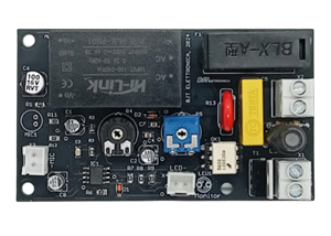
Rhythmic Bass Light - Music Reactive Lamp Controller 300W
Rhythmic Bass Light - Emphasize the rhythm of your music
Elektor Project #10 | By Giuseppe La Rosa (Italy)
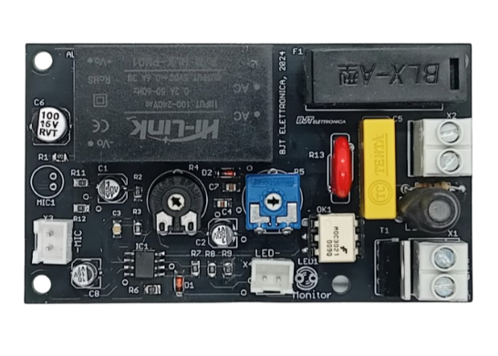
This Rhythmic Bass Light controller drives one or more lamps with a maximum total power of 300W @ 230VAC. It monitors ambient sound using an electret condenser microphone and responds to musical variations in the low frequencies, instantly turning the lamps on to the beat of the music and turning them off with an adjustable delay in the range from 0.1s to 1s. The microphone sensitivity can be easily adjusted.
The device creates a unique lighting effect that can be combined with other traditional disco-style effects or used alone; It is quite accurate in reproducing the musical rhythm and is ideal for parties, nightclubs, light shows and more.
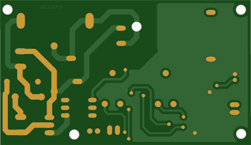
The project mainly uses SMD type components; Their assembly requires specific tools and a certain level of manual skill.
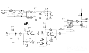
#How it Works - Electrical schematic
The signal is picked up by MIC1, an electret condenser microphone. If necessary, an external auxiliary microphone can be connected by plugging it into the JST-XH connector X3. The signal is then transferred to the operational amplifier IC1A (an LM358D from Texas Instruments) via capacitor C1.
This first op-amp stage (IC1A) is configured as an active low-pass filter. It amplifies the lower frequencies of the audio spectrum with a gain factor equal to the ratio G = (R3 + R4)/R2. Through the trimmer R4, this factor G can be adjusted from a minimum of 2 to a maximum of 100, thus decreasing or increasing the sensitivity of the input filter. The cut-off frequency of the low-pass filter is determined by the combination of C3 plus the sum R3 + R4. The higher the value of C3, the lower the frequency. With R4 short-circuited, this frequency is approximately 70 Hz.
In steady-state conditions (without input signal), the input (pin 5) of the operational amplifier IC1B - positively biased by resistors R6 and R7 - prevails over the inverting input, which is pulled down to a lower potential (+2.5V) by diode D2; therefore, the output of IC1B will be high (+5V).
When IC1A amplifies an audio signal, its output biases diode D1, lowering the voltage at the non-inverting input of IC1B and causing the output state to switch to 0V. As a result, the diode in the optocoupler OK1 turns on, activating triac T1, which in turn activates the lamp. The activation of T1 is also indicated by monitor LED1, which can be routed externally via the JST-XH connector X4.
Subsequently, the series consisting of capacitors C4 and C7 starts to discharge with a time constant determined by their values and that of trimmer R5, causing a decrease in the voltage at the inverting input (pin 6) of IC1B; IC1B will return to the idle state (+5V), deactivating OK1. As expected, the triac ON time is regulated by trimmer R5 within a range from 0.1s to 1s.
Resistors R11, R12 and filter capacitor C8 form a voltage divider that generates the 2.5V bias voltage for the operational amplifiers. Inductor L1 helps reduce noise generated by T1.
Main Features
Drives lamps up to 300W @ 230VAC
Integrated electret microphone MIC1 + external microphone via JST-XH X3
Adjustable low-pass filter ∼70Hz, gain from 2 to 100 via trimmer R4
Adjustable sensitivity and ON time: 0.1s - 1s via R5
Isolated output via optocoupler OK1 and Triac T1 (BT137)
Monitor LED + X4 connector for external LED routing
Isolated 5V power supply via Hi-Link HLK-PM01 module
Bill of Materials
Resistors
(All 0805, unless differently noted)
R1 = 4.7 kΩ
R2 = 10 kΩ
R3 = 22 kΩ
R4 = 1 MΩ, PT10 Trimmer
R5 = 2.2 MΩ, PT10 Trimmer
R6 = 47 kΩ
R7, R8 = 100 kΩ
R9 = 330 Ω
R10 = 330 Ω, 1/4 W, through-hole
R11, R12 = 1 kΩ
R13 = 10D391k Varistor
Capacitors
C1, C2 = 1 μF, 50 V (4x5)
C3 = 10 nF (0805)
C4, C7 = 470 nF (0805)
C5 = 100 nF, 275 VAC
C6 = 100 μF, 10 V (6x5)
C8 = 10 μF, 16 V (4x5)
Inductors
L1 = 4.7 μH
Semiconductors
IC1 = LM358D, SMD, Texas Instruments
OK1 = MOC3021 Opto-coupler
T1 = BT137 Triac
D1, D2 = 1N4148 Diode (Mini-MELF)
LED1 = Blue LED, 5 mm
Others
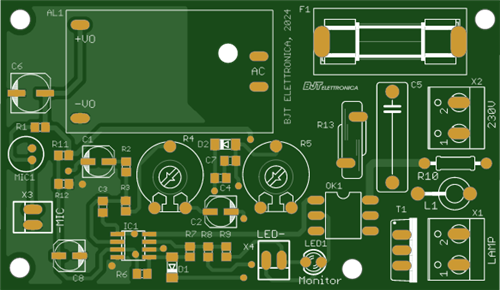
AL1 = HLK-PM01 AC-DC PSU Module
X1, X2 = 2-pole screw terminal
X3, X4 = 2-pole JST-XH connector, PCB type
F1 = 200 mA T
5 × 20 Fuse holder, PCB type
Rhythmic Bass Light - Music Reactive Lamp Controller 300W
Project images are for reference only. Actual production is based on the manufacturing files on the project page.
Please review the designer's notes (e.g., PCB thickness) and select the appropriate options.
PCBWay is not responsible
for issues caused by unsuitable parameter selections.
For more important ordering information, please refer to
Read More









Raspberry Pi 5 7 Inch Touch Screen IPS 1024x600 HD LCD HDMI-compatible Display for RPI 4B 3B+ OPI 5 AIDA64 PC Secondary Screen(Without Speaker)
BUY NOW


- Comments(0)
- Likes(0)
More by GIUSEPPE LA ROSA
-
 DC-DC 3A Adjustable Step-Down Converter LM2576-ADJ - 5-24V to 3-23V - 88% Efficiency
Upgrade your fixed-voltage sources!Transform any 5-24V DC (battery or fixed PSU) into adjustable 3-2...
DC-DC 3A Adjustable Step-Down Converter LM2576-ADJ - 5-24V to 3-23V - 88% Efficiency
Upgrade your fixed-voltage sources!Transform any 5-24V DC (battery or fixed PSU) into adjustable 3-2...
-
 Rhythmic Bass Light - Music Reactive Lamp Controller 300W
Rhythmic Bass Light - Emphasize the rhythm of your musicElektor Project #10 | By Giuseppe La Rosa (I...
Rhythmic Bass Light - Music Reactive Lamp Controller 300W
Rhythmic Bass Light - Emphasize the rhythm of your musicElektor Project #10 | By Giuseppe La Rosa (I...
-
 T3 Surge Protection - Type 3 SPD for Sensitive Equipment
Type 3 Surge Protection - Spike Suppressor for Sensitive EquipmentBy Giuseppe La Rosa, Viagrande (It...
T3 Surge Protection - Type 3 SPD for Sensitive Equipment
Type 3 Surge Protection - Spike Suppressor for Sensitive EquipmentBy Giuseppe La Rosa, Viagrande (It...
-
Programmable Mist Maker - XIAO / QT PY Extension
2371 2 2 -
RadioHAT - Raspberry Pi radio development platform
2054 0 4 -
-
-
-
ARPS-2 – Arduino-Compatible Robot Project Shield for Arduino UNO
4207 0 6 -
A Compact Charging Breakout Board For Waveshare ESP32-C3
4984 3 8 -
AI-driven LoRa & LLM-enabled Kiosk & Food Delivery System
5749 2 2 -