
|
|
ADXL345Analog DEvices
|
x 1 | |
|
|
LTC2990CMS#PBFADI(亚德诺)
|
x 1 | |
|
|
I2C SH1106 Display Oled Azul 128×64 1.3 ” |
x 1 |

|
Altium DesignerAltium Designer
|
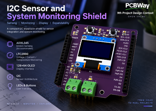
I2C Sensor and System Monitoring Shield
I2C Sensor and System Monitoring Shield
1. Project Overview
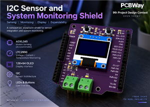
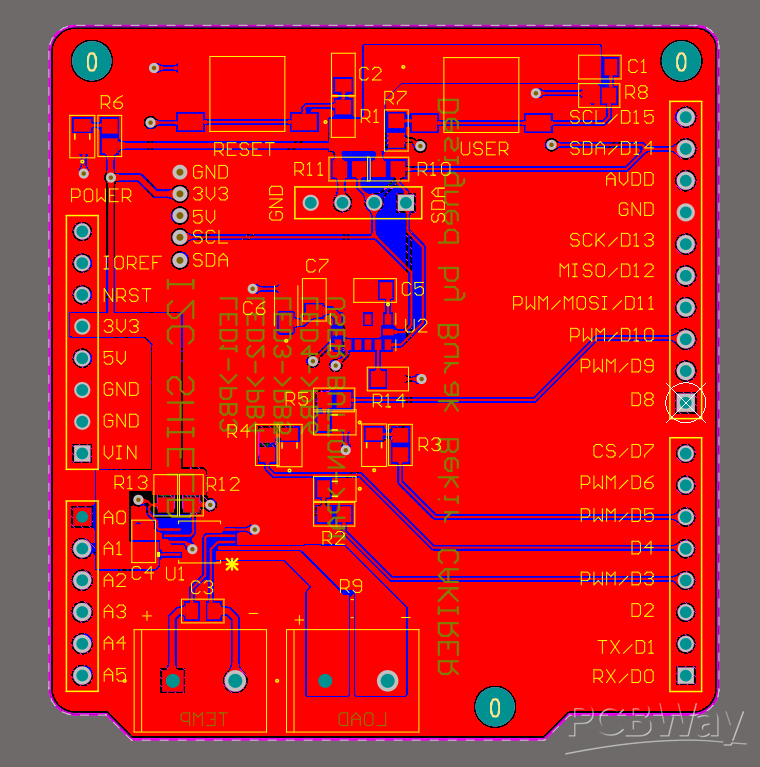
This project is a custom two-layer expansion shield designed to combine sensor acquisition, electrical monitoring, display functionality, and user interaction on a single PCB.
The main objective was to create a compact hardware platform that can be connected to a compatible development board through standard headers while keeping the sensing and monitoring peripherals organized on one board.
The shield integrates an ADXL345 three-axis accelerometer, an LTC2990 voltage/current/temperature monitoring IC, a 128×64 OLED interface, user LEDs, push buttons, and external screw-terminal connections.
The PCB was designed in Altium Designer. The current version has completed the schematic design and PCB layout stages. It has not yet been fabricated or assembled, so the project is presented as a hardware design rather than as a physically validated prototype.
2. Why I Designed This Board
When working with embedded systems, sensors and monitoring devices are often connected individually using jumper wires or separate breakout boards. This is useful during early prototyping, but it can quickly result in a complicated setup.
I wanted to design a single PCB that brings several commonly useful functions together:
• Motion sensing
• Voltage monitoring
• Current monitoring
• Temperature monitoring
• I2C communication
• OLED display connectivity
• User buttons
• Status and user LEDs
• External electrical connections
The project was also an opportunity for me to practice the complete PCB design workflow in Altium Designer, including schematic capture, component selection, footprint assignment, component placement, routing, copper pours, design-rule checking, and manufacturing-output generation.
3. System Architecture
The board is organized primarily around an I2C communication architecture.
The host development board provides the main processing functionality. The shield itself does not contain an onboard microcontroller.
The main I2C peripherals are:
ADXL345
A three-axis digital accelerometer used for motion and acceleration sensing.
LTC2990
A monitoring IC used in the design for voltage, current-related, and temperature measurements.
128×64 OLED
An external display interface connected through the I2C bus for presenting sensor and system information.
The SDA and SCL signals are distributed through the shield to the relevant peripherals. Pull-up resistors are included for the I2C communication lines.
4. ADXL345 Accelerometer Section
The ADXL345 provides three-axis acceleration measurement and communicates with the host through I2C.
The section includes the required supply connections and local decoupling components. The PCB placement was designed so that the associated capacitors remain close to the device supply pins.
This part of the board can be used for motion sensing, orientation-related experiments, vibration observation, and general embedded sensor development.
5. LTC2990 Monitoring Section
The LTC2990 section provides the electrical and temperature monitoring functionality of the shield.
The circuit includes external measurement connections through screw terminals and a low-value current-sense resistor. This allows the monitoring section to support voltage and current-related measurements while also providing temperature-monitoring capability.
Local decoupling and I2C pull-up components are placed around the monitoring IC.
6. OLED and User Interface
A 128×64 OLED module interface is included so that measured or processed information can be displayed directly by the host system.
The shield also contains:
• One power indicator LED
• Multiple user LEDs
• One user push button
• One reset push button
These components provide simple visual feedback and manual interaction during development and testing.
7. PCB Design
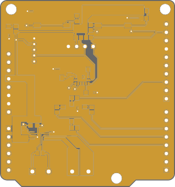
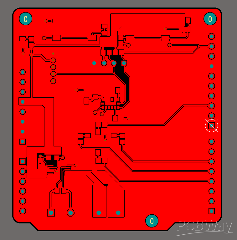
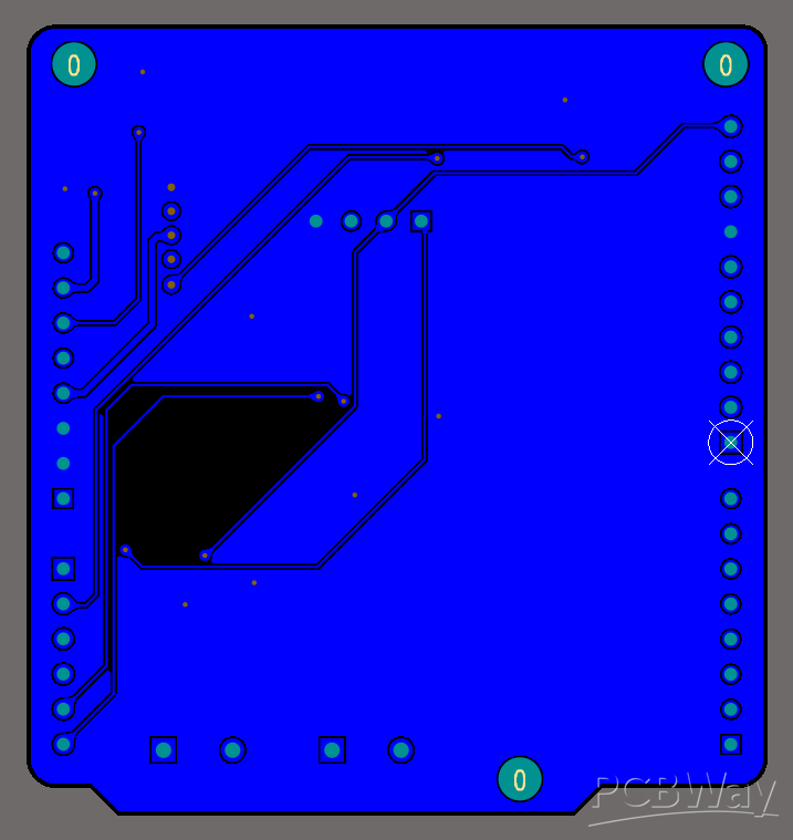
The board was designed as a two-layer standard PCB using Altium Designer.
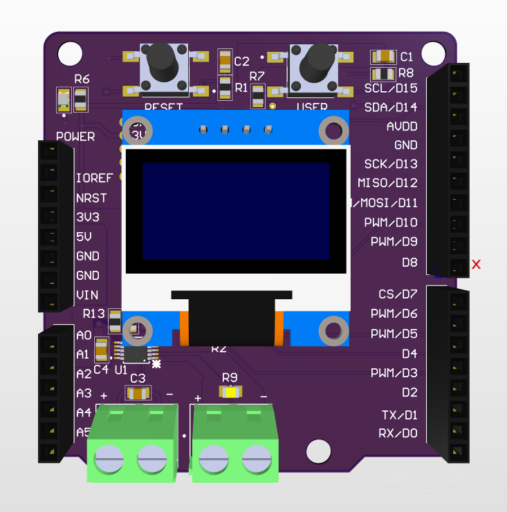
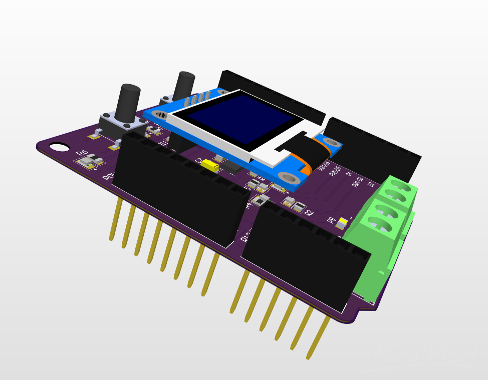
The layout combines surface-mount and through-hole components. 0805 passive components are used throughout much of the design, while development-board headers and screw terminals provide mechanical and electrical connectivity.
During placement, the PCB was divided into functional regions including:
• User controls
• OLED interface
• Sensor circuitry
• Monitoring circuitry
• External connectors
• Development-board headers
Signal routing is distributed between the top and bottom copper layers, and copper pours are used across the board.
Particular attention was given to local decoupling placement, I2C signal routing, connector accessibility, and keeping the functional sections visually organized.
8. Manufacturing Outputs
After completing the PCB layout, manufacturing files were generated directly from Altium Designer.
The project package includes:
• Gerber X2 files
• PTH and NPTH drill data
• Bill of Materials
• Schematic documentation
• PCB layout images
• 3D PCB renders
These files allow the design to progress from the PCB-design stage toward fabrication and assembly.
9. Current Project Status
The schematic and PCB layout are complete and the manufacturing outputs have been generated.
At the time of this submission, the PCB has not yet been fabricated, assembled, or electrically validated. Therefore, no measured performance or physical hardware test results are claimed.
The next development stage would be PCB fabrication, assembly, hardware bring-up, I2C communication verification, sensor testing, and electrical monitoring validation.
I2C Sensor and System Monitoring Shield
Project images are for reference only. Actual production is based on the manufacturing files on the project page.
Please review the designer's notes (e.g., PCB thickness) and select the appropriate options.
PCBWay is not responsible
for issues caused by unsuitable parameter selections.
For more important ordering information, please refer to
Read More









Raspberry Pi 5 7 Inch Touch Screen IPS 1024x600 HD LCD HDMI-compatible Display for RPI 4B 3B+ OPI 5 AIDA64 PC Secondary Screen(Without Speaker)
BUY NOW


- Comments(0)
- Likes(0)
More by Burak Bekir ÇAKIRER
-
Programmable Mist Maker - XIAO / QT PY Extension
2184 2 2 -
RadioHAT - Raspberry Pi radio development platform
1872 0 4 -
-
-
-
ARPS-2 – Arduino-Compatible Robot Project Shield for Arduino UNO
4064 0 6 -
A Compact Charging Breakout Board For Waveshare ESP32-C3
4817 3 8 -
AI-driven LoRa & LLM-enabled Kiosk & Food Delivery System
5621 2 2 -