By Hesam Moshiri, Anson Bao
The STM8S001J3 is an 8-bit microcontroller that offers 8 Kbytes of Flash program memory, plus an integrated true data EEPROM. It is referred to as a low-density device in the STM8S microcontroller family. This MCU offered in a small SO8N package. In this article, we are going to build a programmable Police LED Flasher device that can be used for vehicles, motorcycles, and bicycles.
[1]: Circuit Analysis
Figure 1 shows the schematic diagram of the device. The heart of this circuit is an STM8S001 microcontroller.

Figure 1
Schematic diagram of the programmable police LED-Flasher
Let’s start the analysis from the power supply unit. C2 and C3 are used to reduce the input voltage noises. Then the voltage is handled to the 78M09 [1] (REG1) regulator. It is used to stabilizes the voltage at 9V. C4 and C6 are used to reduce the regulator’s output noises.
The output of the REG1 is handled to a first-order RC filter (R28 and C5). It helps to reduce the noises even further because this device might be used continuously in a noisy environment such as a vehicle. The best way to examine the behavior of this filter (or other filter types) is to perform a practical measurement. The SDS1104X-E oscilloscope introduced a nice bode plot feature that can perform this useful calculation.
REG2 [2] is used to convert 9V to 5V to supply the STM8s001 MCU [3] (IC1). C7 is a supplementary filtering capacitor for the IC1.
IC1 MCU is programmed using a single SWIM wire. It stands for the Single-Wire Interface Module. It is a high-speed link between the MCU and the programmer/debugger. This pin must be connected to the SWIM pin of the programmer/debugger. The ground pin must also be connected. This completes the connection (P2).
IC2 and IC3 are logic N-Channel SMD Mosfets [4] that are used to turn on/off the LEDs. The gate pins of both MOSFETs have been pulled down using 4.7K resistors to avoid unwanted triggering (R13, R14). SW1 is a tactile push button that is used to switch between flasher programs. R27 is a pull-up resistor and C8 reduces the possible push-button debouncing noises.
R1 to R26 resistors are used to limit the LEDs current. In each part, I have put 3 LEDs in series that are connected to the +9V rail (Figure 2). The characteristics of LEDs vary from manufacturer to manufacturer. Therefore we can not assign a fixed limiting series resistor for all circumstances. The maximum tolerable current of a 5mm LED is around 25mA. Therefore the resistor value that could limit the current to somewhere around 15mA (a bit higher than a half) looks sufficient and does not affect the LEDs’ lifetime and does not significantly decrease the LED brightness.
You can start from a 100-Ohm resistor and increase it and simultaneously monitor the current. In my case, I read 15mA by using a 180-ohm resistor.

Figure 2
Finding the best resistor value for the series LEDs
[2]: PCB Layout
Figure 3 shows the PCB layout of the flasher (last revision). It is a single layer PCB board. Except for LEDs, all components are SMD and soldered on the copper side.
In the design process of this schematic and PCB, I used several pre-made libraries from SamacSys. IC1 [5], IC2 [6], IC3 [7], REG1 [8], and REG2 [9] are installed using the SamacSys libraries and its Altium Designer plugin [10] (Figure 4). It saved a lot of my design time. I always make mistakes when I design the libraries from scratch that ruin my day and PCB prototypes. These libraries are free and more importantly, they follow IPC footprint standards.
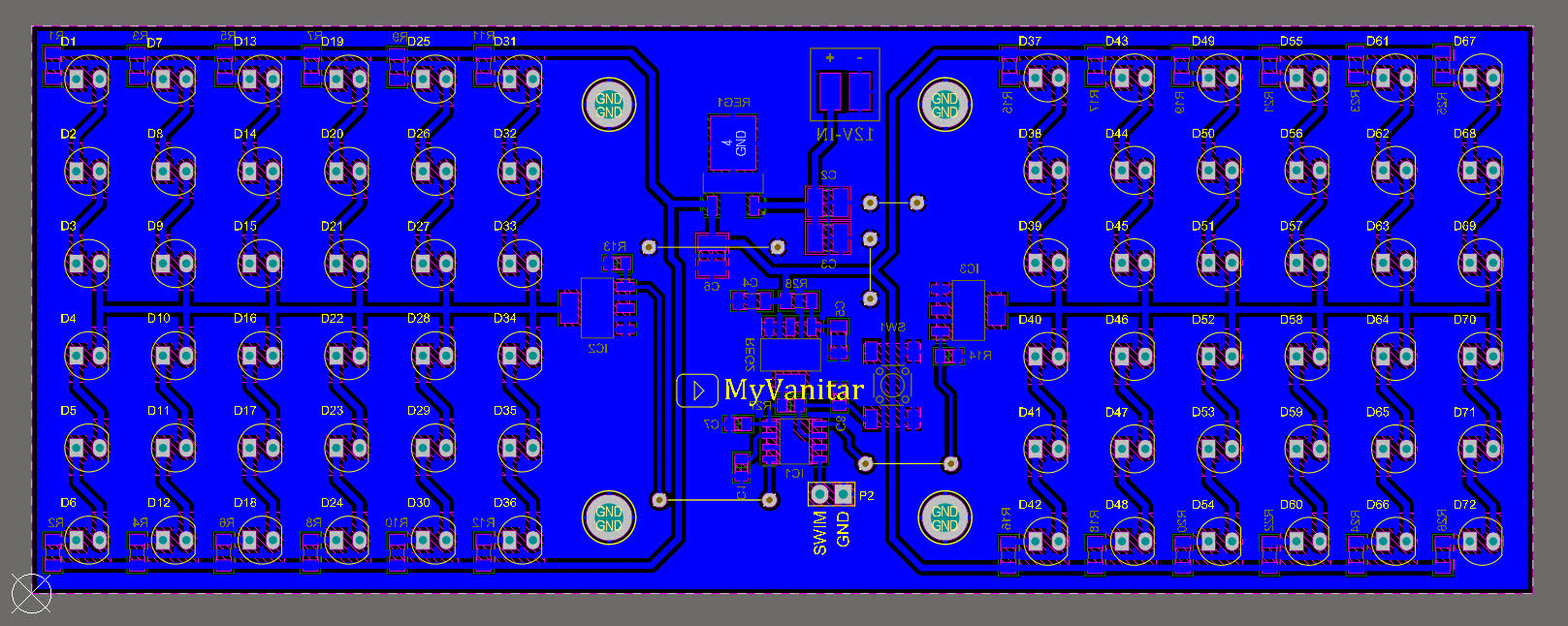
Figure 3
The PCB layout of the Police-Flasher circuit (last revision)

Figure 4
Selected components in the SamacSys Altium plugin
Figures 5 and 6 show the 3D views of the final revision of the PCB board.
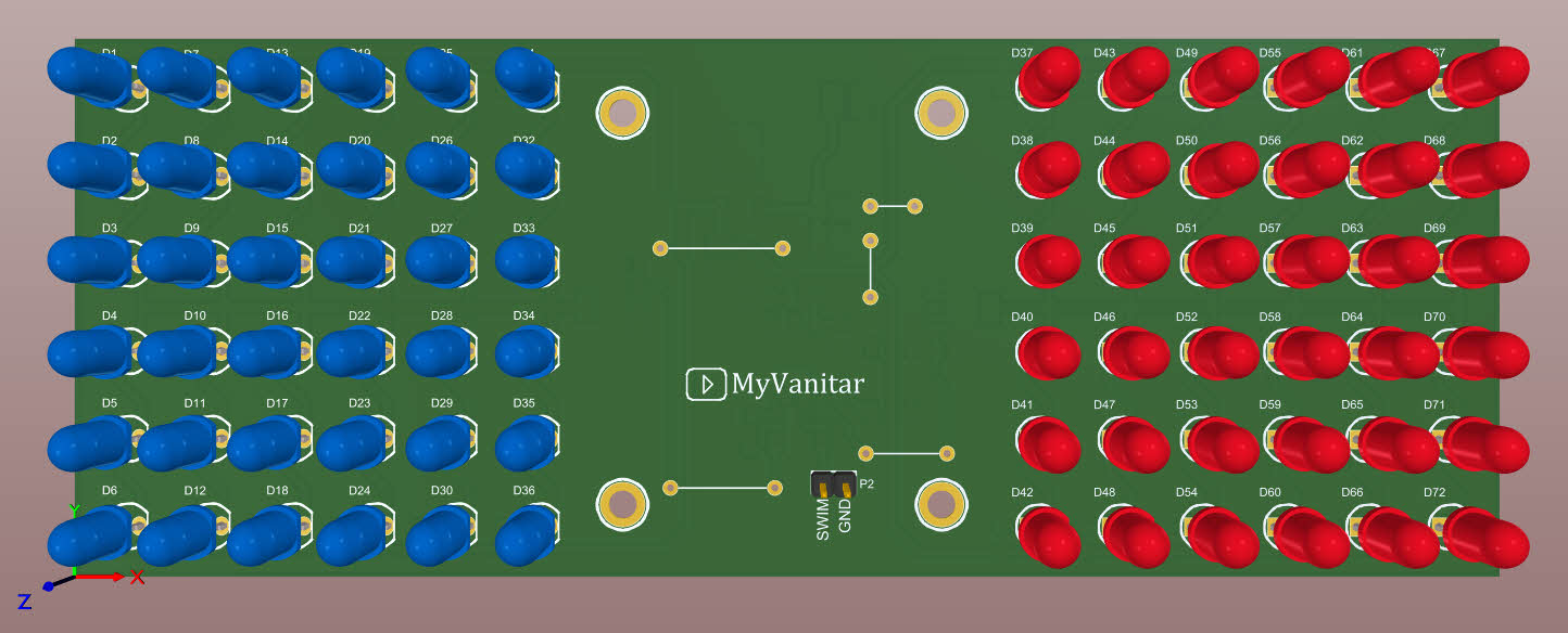
Figure 5
A 3D view of the PCB board from the top (last revision)

Figure 6
A 3D view of the PCB board from the bottom (last revision)
Picture 7 shows an image of the first tested PCB prototype. I ordered it on the PCBWay and I got 5 boards at the same price. As you can see the build quality is fine.
In the last revision, I have modified some component footprints (all are SMD except LEDs) and moved the supply wires to the bottom side. You will solder the 12V supply wires directly on the PCB board.

Figure 7
The first prototype of the flasher board
[3] Software
STM8 MCUs are nice chips, but still, the STM8CubeMX does not fully support them. It means the software does not generate the code for STM8s yet. However, you can use ST Visual Develop (STVP) as a compiler and pre-written libraries for the STM8s (STSW). Figure 8 shows the STVP IDE. You also need to install the COSMIC STM8 to be used as a compiler by the STVP.
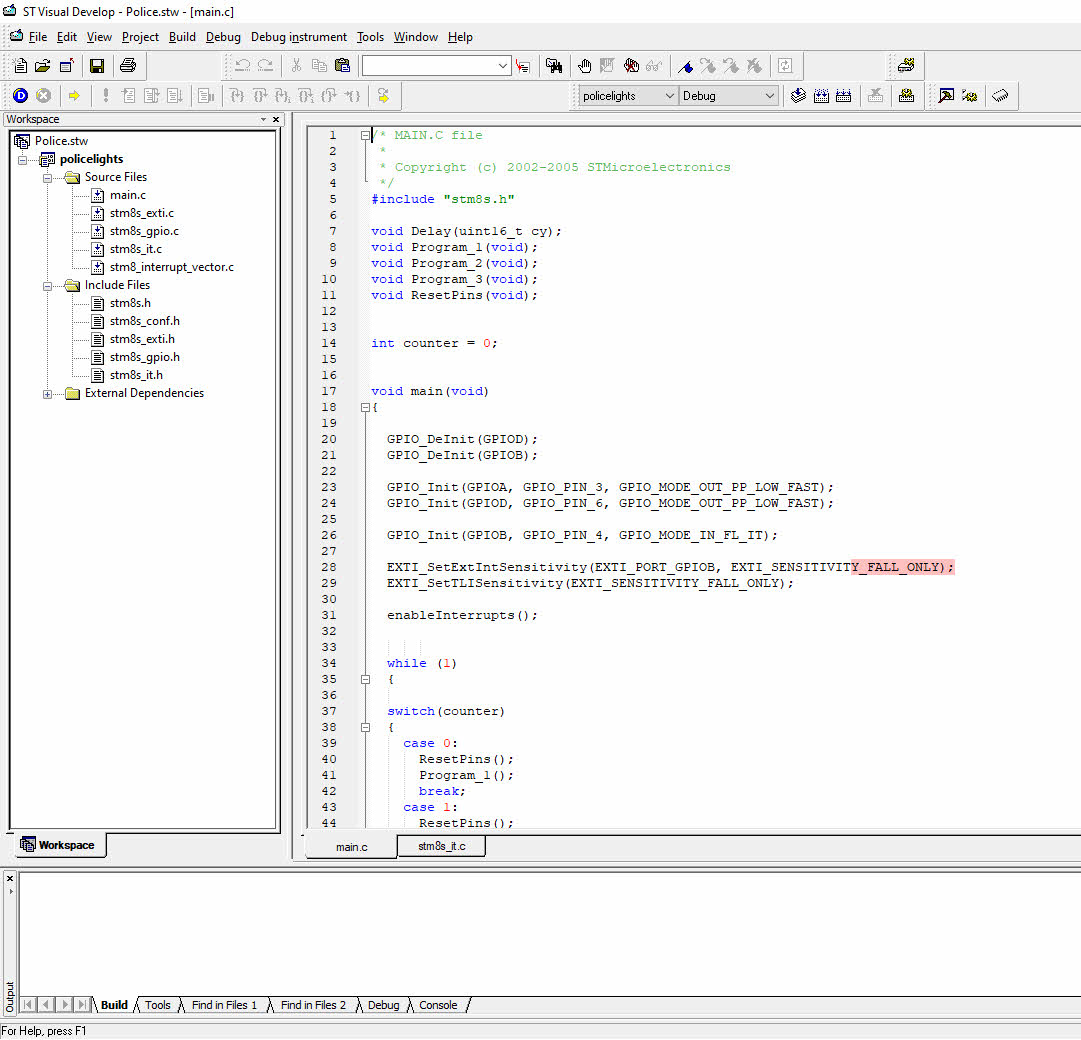
Figure 8
The ST Visual Develop IDE
I used the GPIO and external interrupt libraries to write three flashing programs. The software is freely available. You can extend the code and add your own programs as well. For more description, please check the YouTube video.
[4] Assembly and Test
Figure 9 shows the bill of materials. Nothing is special about soldering. Smallest parts are 0805 passive components that you can easily solder using a 0.4mm soldering wire and an ordinary soldering iron.
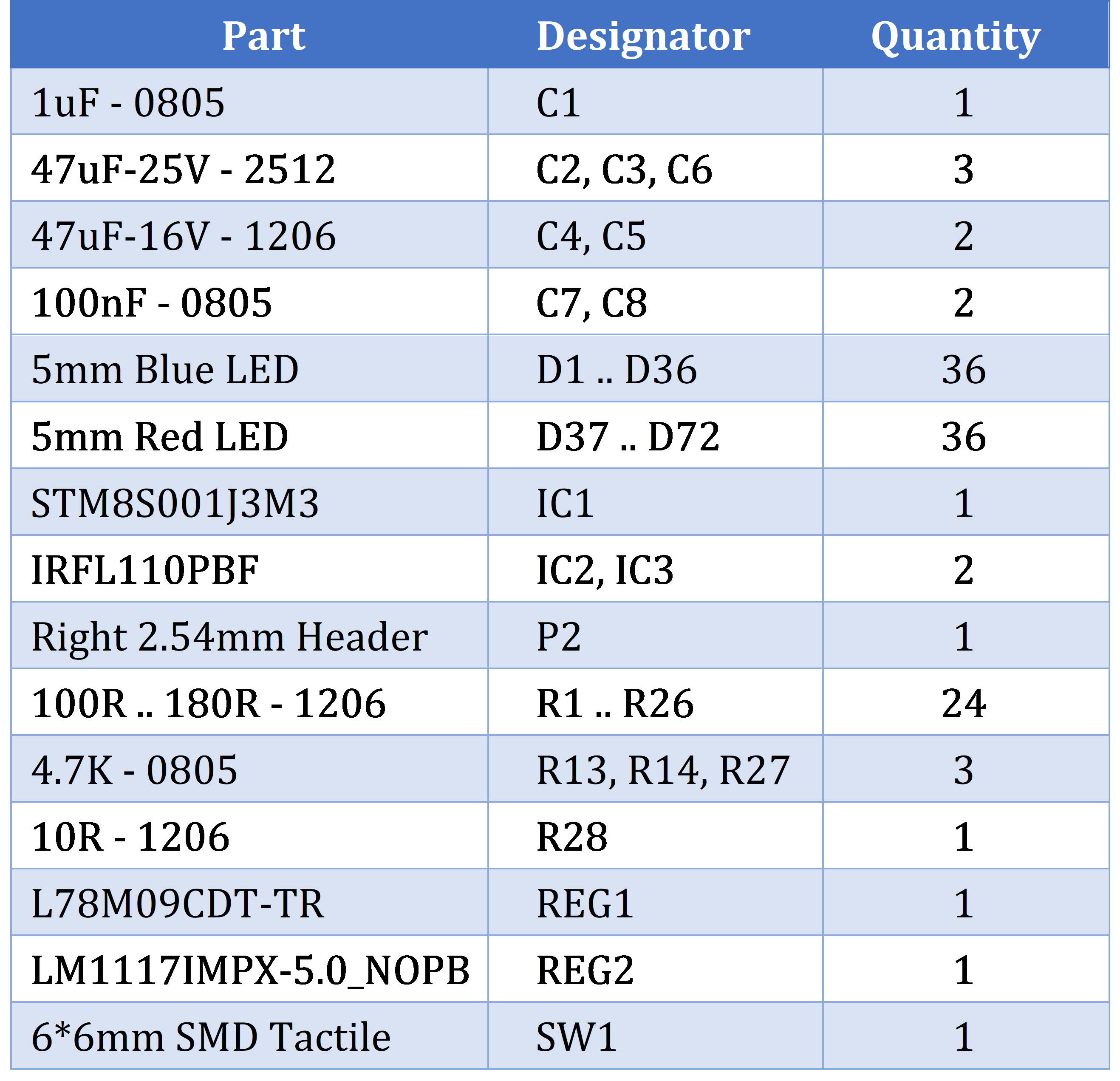
Figure 9
Bill of materials
Be careful about the LEDs’ positive and negative polarities. Try to buy all Blue and Red LEDs from the same manufacturer, otherwise, you might not get smooth and identical lights for all LEDs.
There are some jumpers on the board. Don’t forget to make proper connections using a few zero ohm resistors and similar.
Connect your STM programmer (with the SWIM support) and select the suitable file from the “Release” folder and program the chip. By pressing the push-button, the flashing program changes. You can add your own flashing-routines and program the chip.
Here, you can download the Gerber files or directly order the PCB to be fabricated for you with the highest quality.
You can download the code from here
References
[1]: https://www.st.com/resource/en/datasheet/l78m.pdf
[2]: http://www.ti.com/lit/ds/symlink/lm1117.pdf
[3]: https://www.st.com/resource/en/datasheet/stm8s001j3.pdf
[4]: http://www.vishay.com/docs/91192/sihfl110.pdf
[5]: https://componentsearchengine.com/part.php?partID=1049204
[6]: https://componentsearchengine.com/part.php?partID=4735
[7]: https://componentsearchengine.com/part.php?partID=4735
[8]: https://componentsearchengine.com/part.php?partID=179508
[9]: https://componentsearchengine.com/part.php?partID=235673
[10]: https://www.samacsys.com/altium-designer-library-instructions


