By Hesam Moshiri, Anson Bao
An H-Bridge (Full-Bridge) driver is quite popular in driving loads such as brushed DC motors and it is widely used in robotics and industry. The main advantages of using an H-Bridge driver are: high efficiency, rotation direction change, and braking the motor. In this article/video, I have introduced a complete H-Bridge DC motor driver using four IR3205 power MOSFETs and two IR2104 MOSFET drivers. Theoretically, the above-mentioned MOSFET can handle currents up to 80A, however, in practice we can expect to get currents up to 40A if the MOSFET temp[erature is kept as low as possible, using a big heatsink or even a fan.
[A] Circuit Analysis
Figure 1 shows the schematic diagram of the H-Bridge DC motor driver. As it is clear, the heart of the circuit is two IR2104 MOSFET driver chips.

Figure 1
Schematic diagram of the H-Bridge DC motor driver
I’ve selected 4 IR3205 [1] to do the switching. This MOSFET offers nice characteristics that are essential for this application, very low RDSon resistance, and high current handling capability. According to the IRF3205 datasheet: ”Advanced HEXFET? Power MOSFETs from International Rectifier utilize advanced processing techniques to achieve extremely low on-resistance per silicon area. This benefit, combined with the fast switching speed and ruggedized device design that HEXFET power MOSFETs are well known for, provides the designer with an extremely efficient and reliable device for use in a wide variety of applications. The TO-220 package is universally preferred for all commercial-industrial applications at power dissipation levels to approximately 50 watts. The low thermal resistance and low package cost of the TO-220 contribute to its wide acceptance throughout the industry.”
I’ve selected two IR2104 [2] to drive the MOSFETs. According to the IR2104 datasheet: “The IR2104(S) are high voltage, high-speed power MOSFET and IGBT drivers with dependent high and low side referenced output channels. Proprietary HVIC and latch immune CMOS technologies enable ruggedized monolithic construction. The logic input is compatible with standard CMOS or LSTTL output, down to 3.3V logic. The output drivers feature a high pulse current buffer stage designed for minimum driver cross-conduction. The floating channel can be used to drive an N-channel power MOSFET or IGBT in the high side configuration which operates from 10 to 600 volts.”.
The good news about the IR2104 is that this chip is compatible with both 3.3V and 5V logic levels. Figure 2 shows the basic wiring diagram of the chip. As it is clear, the supply of the chip and load (motor) does not need to be identical, however, both supplies share a common ground.
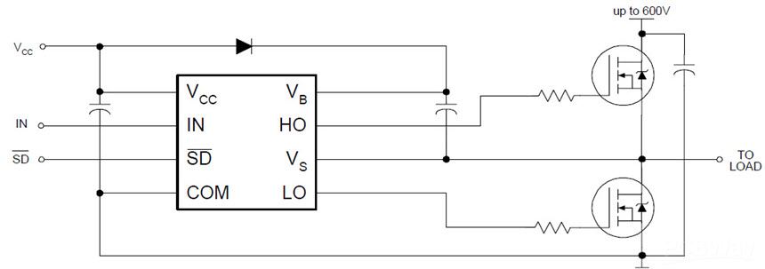
Figure 2
Wiring diagram of the IR2104 MOSFET driver chip
C1, C3, C4, C5, C6, C7, and C9 have been used to reduce the noise. R1 and D2, R2 and D3, R3 and D8, R4 and D9 have been used to damp down the ringing and parasitics that might be introduced by the inductors and capacitors at the ON/OFF times of the MOSFETs. Don’t forget that a MOSFET introduces a capacitance on their gate pin. The 1N4148 diode discharges the gate’s capacitor.
D4, D5, D6, and D7 [3] are used to suppress the DC motor’s reverse current spikes. Internal reverse Shotkey diodes have been embedded in the MOSFETs, however, using these external Shotkey diodes reduce the stress on the internal diodes as well. C2, C8, D1, and D10 are selected according to the datasheet and the application requirements.
P1 is a 5 pins XH connector that is used to apply the chips’ supply and control signals to the board. K1 is a KF45 power connector that is used to connect the motor and motor’s supply wires to the board.
[B] PCB Layout
Figure 3 shows the PCB layout of the H-Bridge DC motor driver. It is a 2 layers PCB board and all component packages are through-hole.

Figure 3
PCB layout of the H-Bridge DC motor driver
Figure 4 shows the 3D views of the PCB board from the top and bottom.
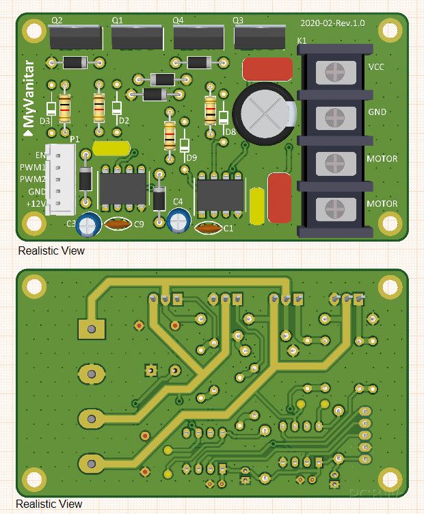
Figure 4
3D views from the top and bottom of the board
I did not have the schematic symbols and PCB footprints of the IR2104 [4] and IRF3205 [5] (component libraries). So I used the SamacSys component libraries and installed the missing libraries using the SamacSys Altium Designer plugin (Figure 5). SamacSys has provided plugins for almost all famous electronic designing software (Figure 6). Interestingly all services are free and libraries do-follow IPC standards. Just you need to download and use your favorite CAD plugin [6]. Another option is to download the libraries from the componentsearchengine.com and import them.

Figure 5
Selected components in the SamacSys Altium plugin
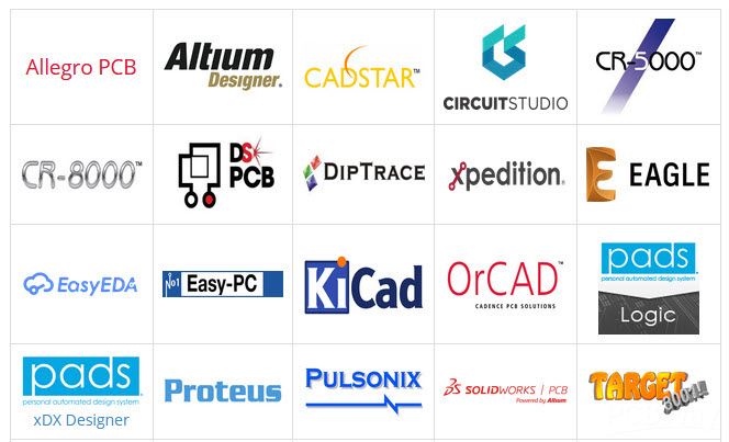
Figure 6
Supported Electronic designing CAD software by the SamacSys plugins
High current carrying tracks are not completely covered by the solder mask. This allows you to strengthen the tracks by soldering or using some thick copper wires. Figure 7 shows these partially exposed tracks.
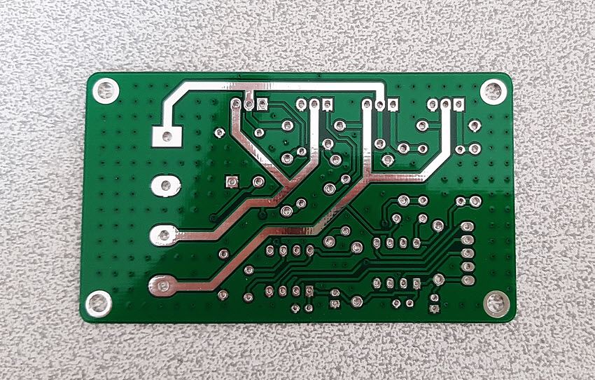
Figure 7
Partially exposed high current carrying PCB tracks
[C] Assembly and Test
Figure 8 shows the assembled unit and figure 9 shows the testing environment. I have programmed the Arduino Uno to control the motor driver board. Also, I have built a simple keypad on a prototyping board to be able to change the speed (using PWM) and rotation direction of the motor.
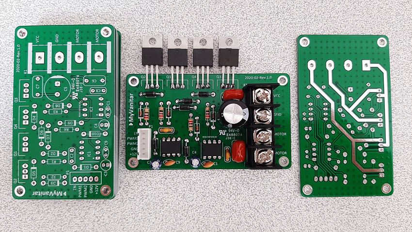
Figure 8
The assembled H-Bridge DC motor driver

Figure 9
The DC motor driver board, Arduino Uno, and the test bench!
All push-buttons are active-low and use internal pull-up resistors of the Arduino. You can consider the Arduino code below:
#include <JC_Button.h>

int PWM_Value;
byte Enable_Pin = 13;
byte PWM1_Pin = 11;
byte PWM2_Pin = 10;
byte PWM_Pin = 11;
Button UP(9, 25, true, true);
Button Down(8, 25, true, true);
Button Left(7, 25, true, true);
Button Right(6, 25, true, true);
void setup() {
pinMode(Enable_Pin, OUTPUT);
pinMode(PWM1_Pin, OUTPUT);
pinMode(PWM2_Pin, OUTPUT);
UP.begin();
Down.begin();
Left.begin();
Right.begin();
digitalWrite(Enable_Pin, LOW);
PWM_Value = 0;
analogWrite(PWM1_Pin, PWM_Value);
analogWrite(PWM2_Pin, PWM_Value);
}
void loop()
{
digitalWrite(Enable_Pin, HIGH);
UP.read();
Down.read();
Left.read();
Right.read();
if (UP.wasReleased() && PWM_Value < 250)
{
 PWM_Value +=5;
}
if (Down.wasReleased() && PWM_Value > 5)
{
 PWM_Value -=5;
}
if (Left.wasReleased())
{
 PWM_Pin = PWM1_Pin;
 analogWrite(PWM2_Pin, 0);
}
if (Right.wasReleased())
{
 PWM_Pin = PWM2_Pin;
 analogWrite(PWM1_Pin, 0);
}
analogWrite(PWM_Pin, PWM_Value);
}
[D] Bill of Materials
Figure 10 shows the bill of materials.

Figure 10
Bill of materials of the H-Bridge DC motor driver
PCB board of the Powerful H-Bridge DC Motor Driver, order from here
[E] References
[1]: IRF3205 Datasheet: http://www.irf.com/product-info/datasheets/data/irf3205.pdf
[2]: IR2104 Datasheet: https://www.infineon.com/dgdl/Infineon-IR2104-DS-v01_00-EN.pdf?fileId=5546d462533600a4015355c7c1c31671
[3]: 1N5819 Datasheet: https://www.diodes.com/assets/Datasheets/ds23001.pdf
[4]: IR2104 Schematic Symbol, PCB Footprint, 3D Model: https://componentsearchengine.com/part-view/IR2104PBF/Infineon
[5]: IRF3205 Schematic Symbol, PCB Footprint, 3D Model: https://componentsearchengine.com/part-view/IRF3205ZPBF/Infineon
[6]: CAD Plugins: https://www.samacsys.com/library-loader-help


