Let’s fight with COVID-19 with Electronics
By Hesam Moshiri, Anson Bao
As we all know, the COVID-19 outbreak hit the world and changed our lifestyle. In this condition, Alcohol and hand sanitizers are vital fluids, however, they must be used properly. Touching alcohol containers or hand sanitizers with infected hands can spread the virus to the next person. In this article, we will build an automatic hand sanitizer dispenser that uses IR sensors to detect the presence of a hand and activates a pump to pour the liquid on the hand. The intention was to find the cheapest and easiest solution and design a circuit. Therefore no Microcontroller or Arduino has been used. Two designs have been introduced and you are free to select and build any of them. The first design uses SMD components and the second design is even simpler. It uses DIP components on a small single layer PCB board.
I. First Design:
[A] Circuit Analysis
You can consider the schematic diagram in figure 1. The P1 connector is used to connect 6V to 12V supply to the circuit. The C6 capacitor has been used to reduce the possible supply noises. The REG-1 is the famous AMS1117 [1] LDO regulator that stabilizes the voltage at 5V.

Figure-1
Schematic diagram of the automatic hand sanitizer dispenser (First Design)
D2 indicates the proper power connection and R5 limits the LED current. D1 is an IR transmitter diode and R1 limits the D1 current, in other words, it determines the sensor’s sensitivity. U1 is the famous 555 [2] timer IC that has been configured to inject a 38KHz pulse to the D1 (transmitter) diode. By turning the R4 potentiometer, you can adjust the frequency. C1 and C2 are used to reduce noise.
U2 is a TSOP1738 IR receiver [3]. According to the TSOP17XX datasheet: “The TSOP17XX series are miniaturized receivers for infrared remote control systems. PIN diode and preamplifier are assembled on the lead frame, the epoxy package is designed as an IR filter. The demodulated output signal can directly be decoded by a microprocessor. TSOP17.. is the standard IR remote control receiver series, supporting all major transmission codes.”
The TSOP1738 introduces an active-low output. It means the output pin of the U2 goes Low in presence of the 38KHz IR light. Therefore I used a cheap P-Channel NDS356 MOSFET [4] to drive the DC motor (liquid pump). D4 is a protective diode against reverse currents of the motor and C8 reduces the motor’s inductive noises. D3 is an LED that indicates the IR reception and activation of the liquid pump. C4 and C5 have been used to reduce the supply noises.
[B] PCB Layout
Figure 2 shows the PCB layout. As it is clear, all components except the IR transmitter diode and the TSOP IR receiver are SMD.

Figure 2
PCB layout of the automatic hand sanitizer dispenser (first design)
I used the SamacSys component libraries (Schematic Symbols and PCB Footprints) for the AMS1117-5.0 [5], LM555 [6], TSOP1738 [7], and NDS536AP [8]. The SamacSys libraries are free and follow IPC footprint standards. Using these libraries significantly reduces the design time and prevents design errors. To install the libraries you can either use a CAD plugin [9] (figure 3) or download them from the component-search-engine. I used Altium Designer, so I preferred to use the Altium plugin.

Figure 3
SamacSys supported CAD plugins and the used components in the Altium Designer’s plugin
Figure 4 and figure 5 demonstrate 3D views of the top and bottom of the PCB board
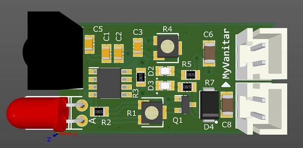
Figure 4
A 3D view from the PCB board (top)

Figure 5
A 3D view from the PCB board (bottom)
[C] Assembly and Test
Nothing is special in the parts assembly process. All components except TR and RE sensors are SMD. I had the intention to quickly test the circuit, so I used a semi-homemade PCB board without solder masks and silkscreen. Your task is much easier with a professional fabricated PCB board :-). Figure 6 shows the prototype.
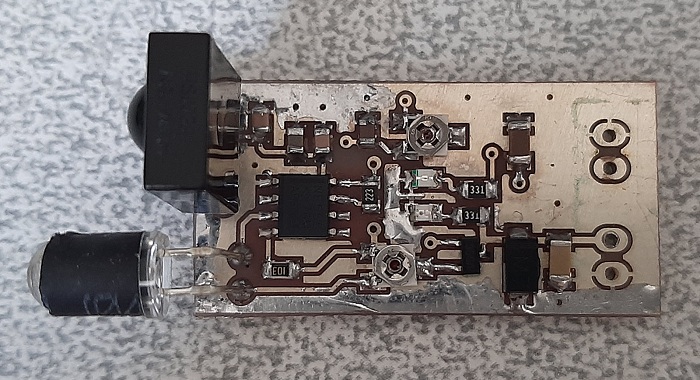
Figure 6
A prototype of the hand sanitizer dispenser (first design) on a semi-homemade PCB board
After assembly, try to adjust the R1 and R4 to find the best fit and detection range. R1 defines the IR power (range) and R4 defined the transmission frequency.
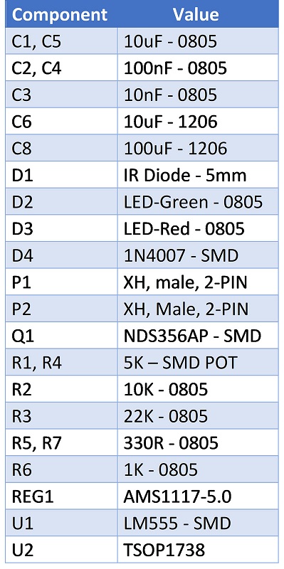
[D] Bill of Materials
II. Second Design
[A] Circuit Analysis
Figure 7 shows the schematic diagram of the device. The P3 connector is used to connect the +5V supply to the circuit. C4 and C5 capacitors are used to reduce the input supply noises. IC1 is the heart of the circuit. It is the famous LM393 comparator [10].
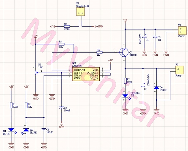
Figure 7
Schematic diagram of the automatic hand sanitizer dispenser (Second Design)
According to the LM393 datasheet: “The LM393 series are dual independent precision voltage comparators capable of single or split supply operation. These devices are designed to permit a common mode range?to?ground level with the single-supply operation. Input offset voltage specifications as low as 2.0 mV make this device an excellent selection for many applications in consumer, automotive, and industrial electronics.”
It is a cheap and handly IC. Generally, I suggest you if your application is a comparator, simply use comparator chips instead of OPAMPs. We used the first comparator of the chip and the R3 potentiometer defines the activation threshold. C2 reduces the possible noises on the middle pin of the potentiometer. D1 is an IR transmitter and D2 is an IR receiver diode. D2 is connected to the negative pin (-) of the comparator to be compared with the positive pin (+) voltage. The output pin of the comparator is active-low, however, it is better to be pulled-up using R4.
Q1 is the famous BD140 PNP transistor [11] that drives the pump (DC motor) and the D3 LED. D4 is a reverse protection diode and C3 reduces the pump inductive noises to not to affect the circuit stability. Finally, P1 is used to connect a blue 5mm LED to indicate a proper power connection.
[B] PCB Layout
Figure 8 shows the PCB layout of the second design. It is a single layer PCB board and all components are DIP. Pretty easy for everyone to build this DIY at home quickly.

Figure 8
PCB layout of the automatic hand sanitizer dispenser (second design)
The same as the first design, I used the SamacSys component libraries (Schematic Symbols and PCB Footprints) for the LM393 [12], and BD140 [13]. SamacSys libraries are free and follow IPC footprint standards. To install the libraries you can either use a CAD plugin [9] (figure 9) or download them from the component-search-engine. Using these libraries significantly reduces the design time and prevents design errors. I used the Altium Designer CAD software, so I preferred to install the Altium plugin.

Figure 9
SamacSys supported CAD plugins and the used components in the Altium Designer’s plugin
Figure 10 shows a 3D view from the assembled PCB board.

Figure 10
A 3D view from the PCB board (top)
[C] Assembly and Test
Figure 11 shows the assembled PCB board. It is a semi-homemade PCB board that I used to quickly test the concept. You can order it for fabrication. Nothing is special in soldering. All components are DIP. Pretty easy. Just do it :-). This design is easier and even cheaper than the first design. So I followed this one and completed the hand sanitizer dispenser device.

Figure 11
A prototype of the sanitizer dispenser (Second design) on a semi-homemade PCB board
Figure 12 shows the selected liquid pump. This is probably the cheapest one in the market, however, I am satisfied with its operation.
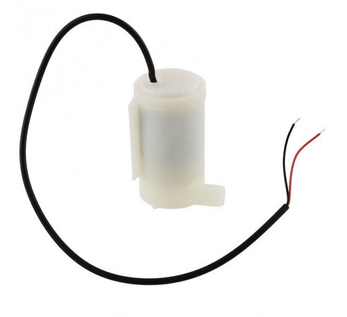
Figure 12
Selected liquid pump to flow the hand sanitizer liquid
Finally, figure 13 shows the complete hand sanitizer dispenser. You can select any similar glass or plastic container, such as a plastic coffee storage container. My selected one is a glass sauce container :-). I used a simple copper wire to bend and hold the hose. Turn the R3 potentiometer from the lowest sensitivity level, and slightly increase it to achieve your desired detection range. Do NOT make it too sensitive because the pump might act spontaneously without any trigger!

Figure 13
A complete DIY of the hand sanitizer dispenser
Figure 14 shows the dispenser in the dark. The blue LED’s light (P1) gives an attractive view that should be mounted on the container lid.
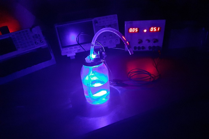
Figure 14
Hand sanitizer dispenser view in the dark
[D] Bill of Materials

First Design: Order the PCB board to be fabricated with the highest quality or download the Gerbers
Second Design: Order the PCB board to be fabricated with the highest quality or download the Gerbers
References
[1]: AMS1117-5.0 Datasheet: http://www.advanced-monolithic.com/pdf/ds1117.pdf
[2]: LM555 Datasheet: http://www.ti.com/lit/ds/symlink/lm555.pdf?&ts=1589508422474
[3]: TSOP1738 Datasheet: https://eu.mouser.com/datasheet/2/427/introductionpartnumbers-1766653.pdf
[4]: NDS356 Datasheet: https://eu.mouser.com/datasheet/2/308/NDS356AP-D-1813031.pdf
[5]: AMS1117-5.0 Schematic Symbol and PCB Footprint: https://componentsearchengine.com/part.php?partID=2376678
[6]: LM555 Schematic Symbol and PCB Footprint: https://componentsearchengine.com/part.php?partID=380204
[7]: TSOP1738 Schematic Symbol and PCB Footprint: https://componentsearchengine.com/part.php?partID=1116997
[8]: NDS356 Schematic Symbol and PCB Footprint: https://componentsearchengine.com/part.php?partID=840198
[9]: CAD Plugins: https://www.samacsys.com/library-loader-help
[10]: LM393 Datasheet: http://www.ti.com/lit/ds/symlink/lm393-n.pdf?&ts=1589509317025
[11]: BD140 Datasheet: https://www.mouser.com/datasheet/2/149/BD140-888626.pdf
[12]: LM393 Schematic Symbol and PCB Footprint: https://componentsearchengine.com/part.php?partID=298790
[13]: BD140 Schematic Symbol and PCB Footprint: https://componentsearchengine.com/part.php?partID=166782


