By Hesam Moshiri, Anson Bao
This project is only free for personal and non-commercial use
AC loads live with us! Because they are everywhere around us and at least home appliances are supplied with the mains power. Many types of industrial equipment are also powered with the single-phase 220V-AC. Therefore, we frequently face situations that we need to have full control (dimming) over an AC load, such as a lamp, an AC motor, a vacuum cleaner, a drill, … etc.
We should know that controlling an AC load is not as simple as a DC load. We have to use a different electronic circuit and strategy. Moreover, if an AC dimmer designed digitally, it is considered a time-critical application, and the microcontroller’s code must be written carefully and efficiently. In this article, I introduced an isolated 4000W digital AC dimmer that consists of two parts: the mainboard and the panel. The panel board provides two push buttons and a seven-segment display that allows the user to adjust the output voltage smoothly.
Circuit Analysis [mainboard]
Figure-1 shows the schematic diagram of the mainboard. The power and digital circuits are on one board.

Figure 1
Schematic diagram of the AC Dimmer’s mainboard
IC1, D1, and R2 are used to detect zero-crossing points. The zero-crossing points are quite essential for an AC dimmer. IC1 [1] is an optocoupler that provides galvanic isolation. R1 is a pullup resistor that reduces the noise and allows us to capture all changes (both rising and falling edges).
IC3 is a 25A rated Triac from ST [2]. This high current rating allows us to easily reach 4000W dimming power, however, the temperature of the Triac must be kept low and as close to the room’s temperature. If you intend to control high power loads, don’t forget to mount a big heatsink or use a Fan to cool down the component. According to the datasheet, this Triac can be used in a variety of applications: “Applications include the ON/OFF function in applications such as static relays, heating regulation, induction motor starting circuits, etc., or for phase control operation in light dimmers, motor speed controllers, and similar”.
C3 and R6, R4 and C4 are snubbers. In a simple term, Snubber circuits are used to reduce the noise, however for more reading, please consider the AN437 application note from ST [3]. IC3 is a snubber-less Triac, however, I decided to use external snubber circuits as well.
IC2 is an optoisolator Triac [4] that is used to control the IC3. It also makes proper galvanic isolation. R5 limits the diode current of the IC2.
IC4 is the famous AMS1117 3.3V voltage regulator [5] that provides the power for the digital part circuits. C1 reduces the input noise and C2 reduces the output noise. P1 is a 2 pins male XH connector that is used to connect the external power to the device. Any input voltage from 5V to 9V is enough.
IC5 is the STM32F030F4 microcontroller and the heart of the circuit [6]. It provides all instructions to control the load. P2 is a 2*2 male header that provides an interface to program the microcontroller through the SWD.
R7 and R8 are pullup resistors for the pushbuttons. Therefore the pushbutton input pins of the MCU are programmed as active-low. C8, C9, and C10 are used to reduce the noise according to the MCU’s datasheet. L1, C5, C6, and C7 reduce the supply noise, also build a first order LC filter (Pi) to provide stronger filtering for the input noise.
IDC1 is a 2*7 (14 pins) male IDC connector that is used to make a proper connection between the mainboard and the panel board through a 14-way flat cable.
PCB Layout [mainboard]
Figure-2 shows the PCB layout of the mainboard. It is a two-layer PCB design. The power components are through-hole and digital components are SMD.

Figure 2
PCB Layout of the AC Dimmer’s mainboard
As it is clear in the image, the board is divided up into two parts and optically isolated using IC1 and IC2. I also made an isolation gap on the PCB, under IC2 and IC3. The high current carrying tracks have been strengthened using both top and bottom layers and tied up using Vias. IC3 has been placed at the edge of the board, so it is easier to mount a heatsink. You should not have difficulties with soldering the components except for IC5. Pins are thin and close to each other. You should be careful not to make solder bridges between pins.
Using the industrial rated SamacSys component libraries for TLP512 [7], MOC3021 [8], BTA26 [9], AMS1117 [10], and STM32F030F4 [11], significantly reduced my design time and prevented possible mistakes. I can not imagine how much time I was wasting if I was intending to design these schematic symbols and PCB footprints from scratch. To use the Samacsys component libraries, you can either use a plugin for your favorite CAD software [12] or download the libraries from the component-search-engine. All SamacSys services/component libraries are free. I used Altium Designer, So I preferred to use the SamacSys Altium plugin (Figure 3).
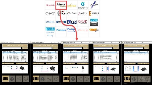
Figure 3
Selected component libraries from SamacSys Altium plugin
Figure 4 shows 3D views from the top and bottom of the board. Figure 5 shows the assembled mainboard PCB from a top view and figure 6 shows the assembled mainboard PCB from a bottom view. The majority of the components are soldered on the top layer. Four SMD components are soldered on the bottom layer. In figure-6, the PCB’s isolation gap is clear.

Figure 4
3D views from the PCB board

Figure 5
Assembled mainboard PCB (top view)

Figure 6
Assembled mainboard PCB (bottom view)
Circuit Analysis [panel]
Figure 7 shows the schematic diagram of the panel. SEG1 is a two digits multiplexed common-cathode seven-segment.

Figure 7
Schematic diagram of the AC Dimmer’s panel
R1 to R7 resistors limit the current to the seven-segment LEDs. IDC1 is a 7*2 (14 pins) male IDC connector, so a 14-way flat wire provides the connection to the mainboard. SW1 and SW2 are tactile pushbuttons. P1 and P2 are 2-pins XH male connectors. I have provided them for the users who intend to use external panel pushbuttons instead of onboard tactile pushbuttons.
Q1 and Q2 are N-Channel MOSFETs [13] that are used to turn ON/OFF each part of the seven-segment. R8 and R9 are pull-down resistors to hold the gate pins of the MOSFETs low, to prevent unwanted triggering of the MOSFETs.
PCB Layout [panel]
Figure 8 shows the PCB layout of the panelboard. It is a two layers PCB board and all components except IDC connector and tactile pushbuttons are SMD.
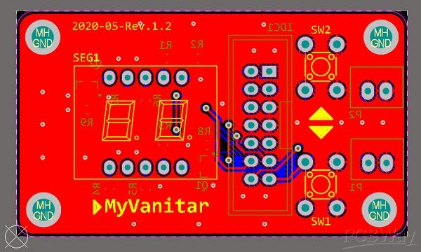
Figure 8
PCB layout of the AC Dimmer’s panelboard
Except for the seven-segment and pushbuttons (if you don’t use external buttons), other components are soldered on the bottom layer. The IDC connector is also soldered on the bottom layer.
The same as the mainboard, I used the SamacSys industrial component libraries (schematic symbol, PCB footprint, 3D model) for 2N7002 [14]. Figure 9 shows the Altium plugin and the selected component to be installed in the Schematic document.

Figure 9
Selected component (2N7002) from the SamacSys Altium plugin
Figure 10 shows 3D views from the top and bottom of the panelboard. Figure 11 shows a top view from the assembled panelboard and figure 12 shows a bottom view from the assembled panelboard.

Figure 10
3D views from the top and bottom of the panelboard

Figure 11
A top view from the assembled panelboard

Figure 12
A bottom view from the assembled panelboard
Results
Figure 13 shows the wiring diagram of the AC Dimmer. If you intended to check the output waveform using an oscilloscope, you must not connect your oscilloscope probe’s ground lead to the dimmer output or nowhere on the mains.
Attention: Never connect your oscilloscope probe directly to the mains. The probe’s ground lead can build a closed loop with the mains terminal. It would blow up everything in the path, including your circuit, probe, oscilloscope, or even yourself!

Figure 13
Wiring diagram of the AC Dimmer
To overcome this problem, you have 3 options. Using a differential probe, using a floating oscilloscope (the majority of the oscilloscopes are ground referenced), using a 220V-220V isolation transformer, or just simply use a cheap step-down transformer, such as 220V-6V or 220V-12V … etc. In the video and figure-11, I used the last method (step-down transformer) to check the output.
Figure 14 shows the complete AC dimmer unit. I’ve connected two boards using a 14-way flat wire.

Figure 14
A complete Digital AC dimmer unit
Figure 15 shows the zero-crossing points and the Triac’s ON/OFF time. As it is clear, both the rising/falling edge of a pulse was considered to not to face any flickering and instability.

Figure 15
Zero crossing points (the purple waveform)
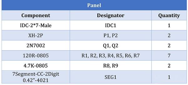
Bill of Materials

It is better to use 630V rated capacitors for C3 and C4.
Mainboard: Download the Gerbers or order the PCB for fabrication [Highest quality]
Panel: Download the Gerbers or order the PCB for fabrication [Highest quality]
Code: Download from here
References
[1]: TLP521 Datasheet: https://www.futurlec.com/Datasheet/LED/TLP521.pdf
[2]: BTA26 Datasheet: https://www.mouser.com/datasheet/2/389/cd00002264-1795706.pdf
[3]: AN437, ST Application Note: https://www.st.com/resource/en/application_note/cd00004096-rc-snubber-circuit-design-for-triacs-stmicroelectronics.pdf
[4]: MOC3021 Datasheet: http://www.farnell.com/datasheets/97984.pdf
[5]: AMS1117-3.3 Datasheet: http://www.advanced-monolithic.com/pdf/ds1117.pdf
[6]: STM32F030F4 Datasheet: https://www.mouser.com/datasheet/2/389/dm00088500-1797910.pdf
[7]: Schematic Symbol and PCB Footprint of TLP521: https://componentsearchengine.com/part/1774908/model/download
[8]: Schematic Symbol and PCB Footprint of MOC3021: https://componentsearchengine.com/part/229006098/model/download
[9]: Schematic Symbol and PCB Footprint of BTA26-600: https://componentsearchengine.com/part/1587919/model/download
[10]: Schematic Symbol and PCB Footprint of AMS1117-3.3: https://componentsearchengine.com/part/656857/model/download
[11]: Schematic Symbol and PCB Footprint of STM32F030F4:https://componentsearchengine.com/part/182014793/model/download
[12]: Electronic CAD Plugins: https://www.samacsys.com/library-loader-help
[13]: 2N7002 Datasheet: https://www.diodes.com/assets/Datasheets/ds11303.pdf
[14]: Schematic Symbol and PCB Footprint of 2N7002: https://componentsearchengine.com/part/228320879/model/download


