This guide aims to provide standard sheet metal bending Design for Manufacturability (DFM) specifications for structural and mechanical designers, helping effectively prevent common issues such as material cracking, springback, tooling interference, hole distortion/stretching, and out-of-tolerance dimensions during the design and drafting stages.
1. Manufacturing Limits & Tolerance Specifications
At the early stage of design, first verify whether part dimensions and manufacturing tolerances align with press brake capabilities and standard sheet stock limits.
Part Size and Bend Length Limits
- The minimum finished part size is 3 × 3 mm (0.118"× 0.118")
- The maximum sheet size depends on the material:
a. Stainless steel and steel: up to 1500 × 3000 mm (59.0" ×118.1")
b. Aluminum: up to 1220 × 2440 mm (48.0"×96.0")
c. Titanium Sheet: up to 1220 × 2440 mm (48.0"×96.0")
d. Copper: up to 600 × 1500 mm (23.6"×59.0")
These dimensions refer to the overall raw sheet size. When sheet cutting is required, a 5 mm margin is reserved along each sheet edge, so the available cutting area is smaller than the nominal sheet size.
For example, a 1500 × 3000 mm sheet provides a theoretical cutting area of approximately 1490 × 2990 mm when a 5 mm margin is required on all four sides.
Bending Height Limits
Bend height is another important design constraint, particularly for small flanges and short bends.
As a general design guideline, the standard minimum bend height is:
Minimum Bend Height ≈ 4 × Material Thickness
- For example, a 1.0 mm sheet should generally have a bend height of at least 4 mm for stable forming with standard tooling.
- A smaller bend height of 3 mm may be possible for sheet thicknesses of 1.0 mm or less when using the appropriate standard tooling.
Design Tip: When possible, use a bend height of at least 4 × the material thickness. If the design requires a 3 mm bend height, verify that the material thickness and standard tooling meet the applicable manufacturing requirements.
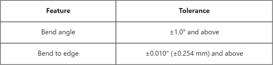
Tolerances for Sheet Metal Bending
Tooling and Special Forming Features
The achievable bend geometry also depends on the available tooling. Very short flanges, closely spaced bends, or unusual geometries may cause tool interference or prevent the part from being formed correctly.
The following features may require dedicated tooling or secondary forming processes:
- Curling
- Roll forming
- Continuous corrugation or complex forming
- Coining
- Hemming
If a part requires special forming operations, confirm the manufacturing method before finalizing the design.
Unproducible Geometries
Some geometries cannot be achieved through standard sheet metal bending due to process limitations:
- Extremely sharp bends with an included angle exceeding 130° due to tooling interference and excessive material deformation
- Near-flat bends below 5°
- Curling, roll forming, and continuous corrugation, which require dedicated forming equipment
- Coining and hemming, which are specialized forming operations
- Joggle bends in plastic sheets such as polycarbonate (PC)
As a general rule, if your part requires any of these features, consider using another manufacturing process, such as stamping or roll forming, or select a different material instead of relying on standard bending.
Common and Unavoidable Bending Marks
Some process-related marks may naturally occur during sheet metal bending:
- Bulging at bend ends — a natural result of the unsupported material at the ends of the bend
- Witness marks — marks left by contact with clamps and tooling, which may become more visible with harder materials
- Minor edge cracking — depending on material thickness and bend angle; sufficient bend relief can help prevent significant cracking
Most standard bending services do not provide cosmetic protection by default. Witness marks are generally considered acceptable when they remain within the specified tolerances and do not affect functionality. If the bend is located on a cosmetic surface, specify the surface requirements when placing the order.
2. CAD File Preparation & Setup Guidelines
2D Vector Files (.dxf / .dwg / .ai / .eps)
- Use a single line to indicate the centerline of each bend. The line color is usually ignored by the system; accurate positioning is what matters.
- Different software may use different conventions for bend lines: Fusion can use solid lines, while SolidWorks / AutoCAD typically use dashed lines. Illustrator / CorelDraw / Inkscape can use solid lines in a separate color. Avoid setting bend lines as software-defined “hidden lines.”
3D Files (.step / .stp)
- Bend lines generally do not need to be drawn separately. Simply create the 3D model in its final bent configuration and upload it.
- Before uploading, verify that the bend angles, inside bend radii, flange orientations, and overall dimensions match the design requirements.
General Recommendations
- Before placing an order, verify each bend angle and flange orientation in the 3D preview. Incorrect bend directions or flange orientations that do not match the assembly requirements are common causes of rework.
- For complex or critical structures, consider producing a prototype first to verify assembly before moving to mass production.
3. Bending Mechanics, K-Factor, and Air Bending
The essence of sheet metal bending is to plastically deform the material under external force. The outer side of the bend is subjected to tension, while the inner side is subjected to compression. Between them is a layer where the material experiences relatively little change in length, known as the neutral axis.
- Neutral Axis: The layer where the material experiences little or no change in length during bending. It is not necessarily located at the center of the material thickness, but is generally positioned closer to the inside surface. Its location is described by the K-factor.
- K-factor: The ratio of the distance from the neutral axis to the inside surface to the material thickness.
- Bend allowance (BA): The arc length of the neutral axis through the bend and is calculated as:
BA = π* (R + K*T) *A / 180
- BA = Bend allowance
- R = Inside bend radius
- K = K-Factor
- T = Material thickness
- A = Bend angle in degrees
- Flat Pattern Length = Sum of straight-section lengths + Bend Allowance. As the K-factor increases, the neutral axis moves farther outward, increasing the material length consumed by the bend region.
Minimum Bend Radius
The inside bend radius is one of the most important parameters in sheet metal bending. A bend radius that is too small increases the tensile strain on the outer surface of the material, increasing the risk of cracking.
Consider the following when designing:
- The minimum bend radius depends on the material, thickness, material condition, bend orientation, and tooling, so a single value should not be applied to all materials.
- Aluminum alloys, high-strength steels, stainless steels, and other materials have different forming characteristics. Select the inside bend radius according to the material specification.
- For materials that are more prone to cracking or for thicker sheets, a larger bend radius should generally be used.
- Do not assume a theoretical R0 bend. Actual bending must account for tooling and the forming capability of the material.
Design Tip: For special materials or small-radius bends, confirm manufacturability with the manufacturer before production.
4. Springback
Springback is the unwanted tendency of sheet metal to return toward its original flat form after the forming process. It is influenced by material properties, bend radius, and thickness.
Compensation methods:
- Overbending: The most direct method—bend the material slightly past the target angle to account for springback.
- Coining: Applies extreme pressure to plastically deform the material through its full thickness, virtually eliminating springback.
- Bottoming: Forces the sheet into full contact with the die, reducing springback compared to air bending.
5. Design Flanges and Bend Geometry
The portion of sheet metal extending from a bend is called the flange. If the flange is too short, the material may not engage properly with the tooling, which can affect bend location and angle accuracy.
- The minimum flange length is generally recommended to be ≥ 2.5–4 × the material thickness and should also be at least greater than half the width of the upper punch tip. A flange that is too short may not be properly supported by the tooling, potentially causing bend-line displacement or defective parts.
- Longer flanges generally provide more stable bending angles, but excessively long unsupported flanges may deform during handling.
Design Checklist:
- Is there sufficient clearance between the flange edge and adjacent cut edges?
- Does the flange interfere with other bends or holes?
- Should the flange end be chamfered or deburred to prevent interference or scratching during assembly?
- For non-rectangular flanges, including angled or curved flanges, verify the final bent configuration in the 3D model and confirm that the tooling can properly access and form the geometry.
6. Bend Relief Design: Prevent Cracking and Deformation
When a bend line terminates inside the sheet rather than extending to an edge, stress concentration can occur at the bend root, increasing the risk of tearing. In such cases, a bend relief is typically added to provide space for material deformation.
- The width and depth of the relief should be determined based on the material thickness, material type, and bend radius.
- For general applications, the relief can be slightly wider than the material thickness, with its depth extending beyond the bend region.
- If a bend line intersects an opening, slot, or internal hole, pay particular attention to stress concentration at the intersection.
- For stainless steel, high-strength steel, titanium, and other materials that are more sensitive to notches, avoid sharp notches at the bend root whenever possible.
Windows, Slots, and Corner Relief
When a window, slot, or cutout is located in the sheet near a bend, its edges can become areas of stress concentration.
- Add radii or reliefs to window corners to avoid sharp corners extending directly into the bend region.
- If a bend line intersects a window, slot, or internal hole, check whether additional relief is required.
- For materials that are prone to cracking, avoid sharp notches at the bend root.
Design Principle: Whenever a bend line does not terminate at the sheet edge and both ends of the bend remain within the sheet, check whether a Bend Relief or Corner Relief is required.
7. Hole and Cutout Placement Near Bend Lines
Holes, slots, and other cutouts located too close to a bend line may stretch, deform, or even tear during bending.
As an initial design guideline:
- Keep holes and other features at least 2 × material thickness away from the bend line as a starting point for evaluation.
- For high-strength materials, small bend radii, or large holes and slots, consider increasing the clearance.
- If a feature must be located close to the bend region, consider adding relief, modifying the feature shape, or changing the structure to reduce local stress.
- Do not consider only the distance from the hole center to the bend line. The actual distance between the hole edge and the bend region should also be considered.
Threaded Inserts and PEM Components
Flanged holes, threaded holes, PEM components, and similar features should not be placed too close to the bend region.
When using press-fit nuts, studs, or other embedded components, verify:
- Whether the components will interfere with the tooling after bending
- Whether the components will be subjected to bending forces
- Whether the installation sequence is appropriate
For components that need to be installed after bending, avoid installing them before bending to prevent component damage or interference with the forming process.
8. Material Grain Direction and Bend Orientation
Sheet metal generally has a rolling direction, also known as the grain direction. The material may have different ductility and cracking behavior depending on the bending direction relative to the grain.
Pay particular attention to the grain direction when working with:
- Small bend radii
- Thicker sheets
- High-strength materials
- Materials with relatively low ductility
- Cosmetic parts where surface cracking is a concern
For critical parts, determine the appropriate bend orientation according to the recommendations of the material supplier or manufacturer. For materials that are prone to cracking, avoid bending in an unfavorable direction with a small bend radius whenever possible.
9. Sheet Metal Bending Design Checklist
- Have you confirmed the material and sheet thickness?
- Have you selected an appropriate inside bend radius based on the material and thickness?
- Have you confirmed the minimum flange length?
- Have you checked whether Bend Relief is required where the bend line terminates inside the sheet?
- Are holes, slots, and other features sufficiently far from the bend region?
- Have radii or reliefs been added to sharp corners of windows and cutouts?
- Have you checked for interference between adjacent bends and between bends and other features?
- Have you considered the effect of material grain direction on bend cracking?
- Are the bend angles and part dimensions within the manufacturer's manufacturing capabilities?
- Have reasonable tolerances been specified for critical assembly dimensions?
- Have you confirmed the allowable witness marks and surface effects for cosmetic parts?
- Have you verified the bend direction, angle, and flange orientation for each bend in the 3D preview?



