printed circuit boards are the backbone of electronic products. They are used to support and connect electronic components. The connection is done using electronic traces that are etched from copper sheets laminated onto a nonconductive substrate. The advantage of pcbs is that once the initial upfront expense of creating a prototype has been made, they are very reliable in volume production. Once ramped up in high volume, the cost for pcbs goes down substantially.
circuit boards are made with copper conductors separated by insulating materials which are typically resin systems with a reinforcement material to add strength and stability. The most prevalent materials are FR-4 Epoxy systems (which means Flame Retardent) reinforced with layers of woven glass cloth, but other resin systems are available like Polyimide (Kapton) or PTFE (Teflon), or with more exotic reinforcements like Kevlar or quartz. A variety of options have been developed to enhance specific desired properties (for example, better thermal performance or lower signal loss), but of course they are more expensive than common FR-4 materials.
FR4
FR stands for Fire Retardant. FR4 is a glass fiber epoxy laminate. It is the most commonly used pcb material. A 1.60mm FR4 uses 8 layers of (7628) glass fiber material. The red UL/manufacturers logo is in the middle (layer 4). There are two types of logos: red and blue logos. Red is UL94-V0, blue is UL94-HB. If you have a blue logo material, it is either XPC (phenolic) or G10 (glass epoxy); these are older materials. The main usage of G10 nowadays is for thin watch circuit - since it is very punchable. In 1.50/1.60mm FR4 the logo is in the middle layer (layer 4) of the common 8 layer construction.
FR-4 is made of woven fiberglass cloth with an epoxy resin binder that is flame resistant (self-extinguishing). Note that FR-4 is a specification – not a product in itself.
FR-4 glass epoxy is a popular and versatile high pressure thermoset plastic laminate grade with good strength to weight ratios. With near zero water absorption, FR-4 is most commonly used as an electrical insulator possessing considerable mechanical strength. The material is known to retain its high mechanical values and electrical insulating qualities in both dry and humid conditions. These attributes, along with good fabrication characteristics, lend utility to this grade for a wide variety of electrical and mechanical applications.
FR-4 is the primary insulating backbone upon which the vast majority of rigid printed circuit boards (PCBs) are produced. A thin layer of copper foil is laminated to one, or both sides of an FR-4 glass epoxy panel. These are commonly referred to as “copperclad laminates.”
FR-4 copper-clad sheets are fabricated with circuitry etched into copper layers to produce printed circuit boards. More sophisticated and complex FR-4 printed circuit boards are produced in multiple layers, aka “multilayer circuitry”.
FR-4 is a worldwide standard PCB dielectric used in quality PCBs. FR-4 is similar to CEM-3 and is part of a family of laminates of varying specification and cost. See also printed circuit board.
Standard rigid FR4
Designed for use in high density multi-layer boards, FR4 is suitable for surface mount multi-layers, MCM-Ls, direct chip attach, automotive and wireless communications. The characteristics of FR4 also make it particularly beneficial in high volume fine line multi-layers and PCMCIA applications.
The predictability and consistency of this material provides for tremendous ease of processing at the circuit board fabrication site, and its electrical and mechanical characteristics make it user friendly for both designers and fabricators of critical circuits.
CEM-3 (CEM - Composite Epoxy Material)
CEM-3 is very similar to FR4. Instead of woven glass fabric a 'flies' type is used. CEM-3 has a milky white color and is very smooth. It is a complete replacement for FR4 and has a very large market share in Japan.
Prepreg
A 'prepreg' is an epoxy coated glass fabric. It has two usages: as a dielectric in multilayer PCBs, and as the raw material for FR4. 8 layers of '7628' prepregs are used in one sheet of 1.60mm FR4. The central layer (number 4) usually carries the red company/UL logo.
Prepregs come in various thicknesses:

PCB materials for Flex and Rigid-flex applications
Flex and Rigid-flex circuit boards have become increasing popular due to their unique applications. Flex and Rigid-flex circuit boards can do what regular standard rigid circuit boards can not do. They can fold, twist, and wrap around tight/small packaging area.
Most flex circuit boards are being manufactured using "Kapton", a material developed by Dupont Corporation. This polyimide film based material is resistant to heat, has dimensional stability and a low dielectric constant of 3.2. There are three variants of the Kapton material:
1. Pyralux LF (Acrylic Base Adhesive-not Flame Retardant)
2. Pyralux FR (Acrylic Base Adhesive-Flame Retardant)
3. Pyralux AP (Adhesiveless-for more Demanding high-performance applications)
PCB materials for RF/Microwave/High Speed applications
As circuit speeds continue to escalate and wireless communications proliferate, the need for a high frequency circuit boards becomes paramount. Here are some typical materials used in high frequency PCB constructions:
Rogers Corporation
5870/5880 series
3003/3006/3010 series
6002/6006 series
4003/4350 series
TMM4/TMM6/TMM10
Arlon
DiClad and CuClad series Park-Nelco
N4000 series/ N5000 series/ N6000 series/ N7000 series/ N8000 series Getek
Loss tangent = .012 (slightly high) (usage in analog circuits up to 1.2 ghz and up to 2.0ghz in digital applications) (Stability in temperature variations good)
Er = 3.5 to 4.3 (at 1.0mhz) (specific Er is dependent on glass-resin- ratio - Er is virtually constant form 1.0mhz to 2.0ghz)
CTEr = +220ppm per degrees C (high). Tg is 180 degrees C.
Electro-deposited Copper only. (helps in peel strength and de-lamination but somewhat limits etch width tolerance due to undercutting).
Hybrid PCB materials
Hybrid circuit boards are a way of reducing cost. It is a process of combining standard FR4 laminate with other RF/microwave/high speed laminate. The technology gives engineer the ability of controlling the design on desired layer(s) yet still reducing cost with standard FR4 on the remaining portion of the circuit boards.
Teflon(PTFE), Rogers, Taconic
PTFE is used as non-stick coating for commercial applications due to its inert molecular structure. Its surface can be “roughened” only through drastic measures. PTFE/woven glass base materials are not surrounded by the myth of something exotic anymore. Asecured manufacturing and defined processing to pcbs are the guarantors for it. Rapid growth ofapplications operating at high frequencies demands a material availability with proven performance over many years. These facts are both given with PTFE/woven glass base materials.
In Rogers’ Advanced Circuit Materials Division, they manufacture high frequency laminates for applications in the wireless base station, aerospace and defense, automotive, high-speed digital and advanced chip packaging industries. All of products are manufactured in an ISO-9001:2008 certified facility with “ahead of the curve” process technology.
Rogers manufacture an extensive 1oz to 10oz.
2. Insulation layer: Insulation is a layer of thermal insulating material with low thermal resistance.Thickness: 0.003 “to 0.006″ inch is the aluminum pcb core technology.
3. Based Layer: a metal substrate,usually aluminum or copper may be chosen.
Features:
● Use of surface mount technology (SMT);
● The circuit design of the thermal diffusion of highly effective treatment;
● Reduce product operating temperature,increase the power density and reliability,extended product life;
● Smaller footprint,lower hardware and assembly costs;
● Replace the fragile ceramic base pcb,better mechanical durability.
As an advocate to promote energy-saving lamps and colorful energy-saving LED lights are very popular by the market, the aluminum pcb used in LED lights have begun a large-scale applications.
An attempt has been made by the electronics industry (a committee of volunteeers organized by the IPC) to classify materials according to their properties and sort them into groups. This has been published as IPC-4101, the Specification for Base. Materials for Rigid and Multilayer Printed Boards, which continues to be expanded and revised as new materials become available. In IPC-4101, materials with similar properties are grouped by number, and each numbered data sheet is referred to in the industry as a "slash sheet". Most material data sheets will list the IPC slash sheet numbers that they conform to.
Laminate materials (also called "cores") are manufactured and sold in large sheets, typically around 36" x 48", and then cut into smaller fabrication panels by the bare board fabricator. They are fully cured and coated with a thin layer of copper on both sides. Pre-Preg materials (sometimes called "B-Stage"), are glass cloths pre-impregnated with resin, but are not fully cured. One or more pre-preg layers will be inserted between each core to complete the layer stackup, and it is these pre-pregs that melt in the lamination press, forming the adhesive that bonds the layers together.
The following characteristics will be more or less important depending on the particular application. They may have to be prioritized to find a balanced solution that meets the cost and performance targets of the product.
Coefficient of Thermal Expansion (CTE)
Most materials expand when their temperature rises, and contract when they cool. CTE is a way of expressing the amount of change in a material's volume during a temperature change, expressed as parts per million per degree centigrade (ppm/%deg;C). One way of classifying materials is by comparing their CTE. Epoxy resin has a CTE (35-45) that is higher than copper (17-18). This would be a mismatch during thermal cycling that could lead to early failures, but the fiberglass reinforcement material has a much lower CTE (5-6) that limits the expansion in the X-Y directions. This added glass brings the overall CTE of a laminate very close to that of copper. Nothing constrains the expansion in the Z-direction, however, so many designers use materials that are rated based on their z-axis CTE. For example, many designers specify materials that expand no more than 3% of their thickness (z-axis) over a temperature change from 50%deg;C to 260%deg;C
Tg - Glass Transition Temperature
As temperature changes, the expansion or contraction of a board material will exhibit a fairly linear rate of dimensional change, as shown in the figure below. At the glass transition temperature, the material changes from being in a hard and relatively brittle condition to being in a viscous or rubbery condition, and the rate of change will vary drastically.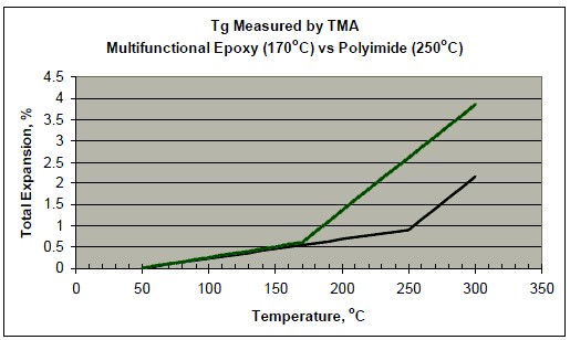
In the figure above, you can see that both materials behave very nearly the same at low temperatures, but the material with a lower glass transition temperature begins to change significantly more above 170°C. Materials with low Tg might be okay for applications that use eutectic solder (which melts at 183°C) but might not be acceptable for lead-free solders that require temperatures above 220°C.
Td - Decomposition Temperature
The temperature at which a base laminate material experiences an established percentage of weight loss using Thermogravimetric Analysis (TGA). Td is the temperature at which a material begins to degrade, most commonly specified as the temperature at which a material has lost 5% of its original weight due to decomposition. In the past, the glass transition temperature (Tg) has been used to classify materials by their thermal properties, but at the higher temperatures required for lead-free soldering (to meet RoHS requirements), Td has also proven to be a useful indicator of board material stability.
T266 T288 and T300
T260, T288 and T300 values represent the length of time that a clad laminate will survive a particular temperature (respectively 260°C, 288°C and 300°C) before it begins to delaminate or blister. These values are considered good indicators of the short term resistance of the material to the soldering process.
Dielectric Constant (Er)
The Dielectric constant (or "permittivity") determines the speed at which an electrical signal will travel in a dielectric material. Signal propagation speed is expressed relative to the speed of light in a vacuum, which is defined as having a dielectric constant of 1.00. Higher dielectric constants will result in slower signal propagation speeds. A common dielectric constant for FR4 materials would be in the range of 4.2 to 4.8, but for high-speed applications, materials have been developed that are in the range of 3.0 to 3.6. Other materials may be available with lower Er, but could be a significant cost adder to the product. For designs with Impedance Controlled signals, you will need to know the Dielectric Constant to calculate the appropriate trace widths to use.
Related to dielectric constant is Dissipation Factor, also known as Loss Tangent. This is a measure of the percentage of the total transmitted power that will be lost as power dissipates into the laminate material.
Semiconductor packages serve to protect integrated circuits during shipping and handling and to dissipate heat. The semiconductor packaging market is closely linked to the PCB manufacturing market because packages allow the die to be mounted on the PCB. The package provides protection and insulation. Demand for packaging has been driven by the trends toward miniaturization of ICs, smaller form factors, cost and performance, and the extension of Moore's Law, which dictates that miniaturization or device scaling will lead to more performance at an overall lower cost.
Currently, the global growth of PCBs is being driven by the increased use of multilayered, flexible PCBs. The board density and design complexity keep increasing as electronic companies try to add more features to the product. Electronics designers are trying to design products with higher clock speeds. At higher speeds, speed and power dissipation become an issue requiring the use of advanced materials that can maintain their physical properties under ever more stressful conditions. At the same time, the electronics industry is extremely cost-sensitive. The properties of advanced materials and costs must be in balance.
The following pie charts show world consumption of PCB chemicals and semiconductor packaging materials:

The importance of Asia in the electronics industry cannot be overemphasized. Manufacturing capability in China, Taiwan, the Republic of Korea and Japan makes Asia the center of the industry. Currently, almost all high-volume low-cost production of electronics is conducted in Asia.
Globalization started to affect chemical markets in the mid-1990s. Only fifteen years later, it became standard practice to design and develop a product in one country, manufacture it in another and distribute it globally. Most successful semiconductor and electronic producers established factories in Asia and the materials suppliers followed the lead of their customers. At first it was the availability of low-cost labor and a young workforce that drove companies to Asia, but in the past fifteen years, Asian companies have developed cutting-edge, technologically advanced manufacturing capabilities and large-scale manufacturing facilities.
Globalization is not just about selling goods and services across the globe. It is also about changing demographics and immigration patterns. Companies are now selling and sourcing goods, services and labor all over the globe. This requires rapid, uninterrupted access to information on customers, products, services, markets, competitors, end users and more. This information needs to be timely and personalized. Populations are becoming more mobile and are moving to the centers of production. People want to communicate and collaborate with associates, friends and families. It is a question whether globalization drove demand for communication and information or whether the availability of communication technology drove globalization. Regardless of the argument, in the past fifteen years, communication and information technology and the internet have changed the paradigm and brought the world closer together, launching the age of communication and information. These novel technologies have enabled faster access to information, and empowered communication, collaboration and connectivity. Therefore, these devices will be in high demand and will continue to drive the demand for electronic materials.
This diverse, highly specialized, technology-driven global market is projected to grow at an average annual rate of 4.0% through 2017. After the economic recession in 2009, the global economy has been gradually recovering, especially in emerging countries like China, with a growth rate of 6.9%. In developed countries like the United States, Western Europe and Japan, economic recovery is slower.
About PCBWAY

Since 2003 PCBWAY has been the leading PCB quick turn manufacturer specializing in both Prototype and Production quantities, Initially produced single-sided and double-sided printed circuit boards for the consumer electronics market. PCBWAY is ranked among the top 4 board fabricators in asia and is well-known for its expedited turn time capabilities and its reliable best on-time shipping record.
Today, we have over 450 operators with high modern facilities to manufacture multi-layer PCB up to 12 layers. Backing up with a group of professional engineers, and well established quality system. PCBWay has grown to become a major PCB manufacturer in Asia to serve in diverse customers base such as electronics appliance, communication, educational electronics, power supplies, Automationsetc.
Our mission is to become one of leading PCB manufacturer that provide in high quality product with total customer satisfaction.


