Team Helios Racing
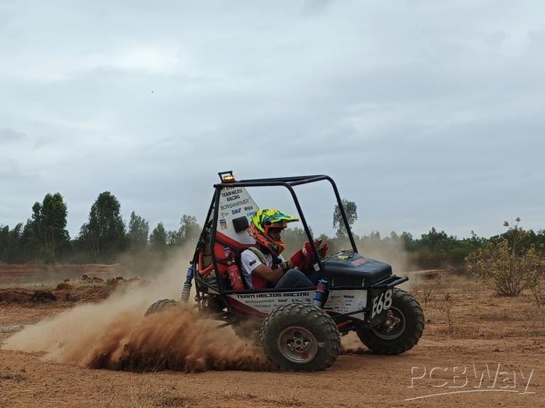
Founded in 2006, Team Helios Racing is the official electric all-terrain vehicle design team of RV College of Engineering, Bangalore. The team is composed of passionate undergraduate students from various engineering disciplines who work together to design, build, and test a fully electric ATV for the SAEINDIA eBAJA competition, one of the largest collegiate engineering competitions in India. Through this project, students gain hands-on experience in real-world engineering challenges such as electric powertrain integration, battery design, suspension systems, vehicle dynamics, and electrical safety systems.
Every year, the competition challenges teams to design and manufacture a rugged off-road vehicle capable of performing reliably in harsh terrains while also demonstrating strong engineering design, manufacturing, cost analysis, and business strategy. Over the years, Helios Racing has developed a culture of innovation, teamwork, and practical learning. The team works through the entire vehicle development cycle including design, simulation, manufacturing, testing, and competition participation.
One important part of our vehicle is the electrical architecture, which manages safety controls, activation logic, and auxiliary functions required for the vehicle to operate. To make the wiring more organized and compact, our team designs custom printed circuit boards (PCBs) that integrate multiple electrical components into a single board. This helps reduce wiring complexity, improves durability in the high-vibration conditions of off-road racing, and makes troubleshooting easier during testing and competition.
Our current vehicle uses two custom PCB circuits, each responsible for an important function in the electrical system.
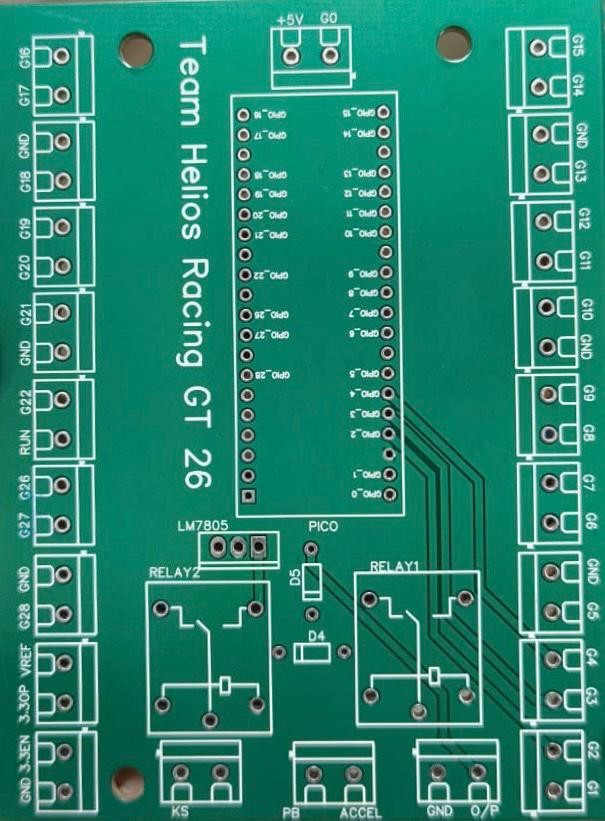
1. Activation Circuit PCB
The activation PCB manages the vehicle start-up logic. In an electric race vehicle, the drivetrain cannot activate immediately when power is turned on. Instead, several safety checks must be satisfied before the vehicle can enter the ready-to-drive state. The activation PCB verifies conditions such as brake pedal engagement, kill switch status, gear position, and accelerator input. Only after these checks are satisfied does the circuit allow the system to power the drivetrain. This ensures that the vehicle operates safely and according to competition safety regulations.
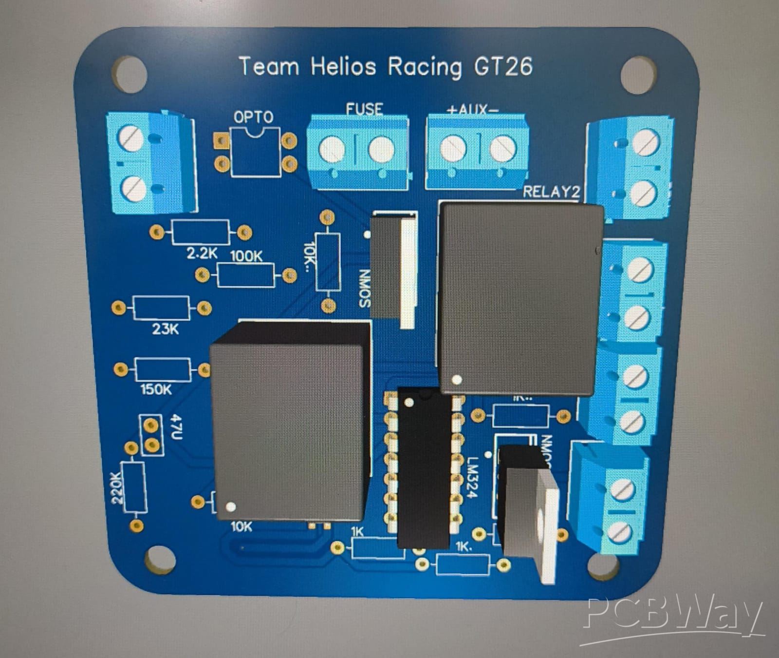
2. Interlock and Reverse Control PCB
The second PCB implements the tractive system interlock and reverse control circuit. The interlock ensures that the vehicle cannot enter the ready-to-drive state if the high-voltage battery pack is disconnected. This is implemented using an optocoupler-based isolation circuit that safely allows the low-voltage system to detect the presence of the high-voltage accumulator. The PCB also controls the reverse light and reverse alarm, which are activated when the motor controller provides a reverse signal, ensuring safety while the vehicle moves backward.
These PCBs play an important role in improving the safety, reliability, and organization of our electrical system. Instead of relying on complex wiring, integrating these circuits onto PCBs allows us to create a compact and durable system that performs consistently under the demanding conditions of off-road racing.
The team would greatly benefit from the support of PCBWay. As a student team working within limited resources, manufacturing reliable PCBs while maintaining tight development timelines can be challenging. Access to high-quality PCB manufacturing and rapid prototyping would allow our team to improve the reliability of our electrical systems and enable students to gain valuable hands-on experience in electronics design and testing.
Apply for sponsorship >>- Comments(0)
- Likes(0)