Smart Tech IoT Storage Locker
Chapter 1: Automating the Modern Laboratory – Overcoming Maker Entropy
1.1 The Maker’s Paradox: Creativity vs. Disorder
In the contemporary technological landscape, a "Maker" is defined by the ability to transform abstract code into tangible reality. However, this transformation is often hindered by a silent adversary: laboratory entropy. Every successful project necessitates a plethora of passive components, microcontrollers, sensors, and actuators. As time progresses, managing this inventory becomes a critical bottleneck. The search for a single component—perhaps a 220Ohm resistor or a specific breakout board—can consume tens of minutes, effectively breaking the flow state that is fundamental to innovation.
This project does not originate merely as an engineering exercise, but as a strategic response to such inefficiency. The objective is to transition from an analog-chaotic laboratory to a centralized IoT (Internet of Things) ecosystem, where the hardware serves creativity, rather than acting as a barrier to it.
1.2 The Vision: The Smart IoT Lab Locker
The concept of the "Smart IoT Lab Locker" is built upon the integration of four fundamental pillars:
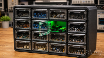
Intelligent Storage: Not mere drawers, but dynamic storage units.
Automated Retrieval: The software interface functions as an intelligent database that "knows" the physical location of every item.
Power Control: The custom PCB electronics ensure that low-level digital logic can interact with high-power physical actuators (12V solenoids) safely and reliably.
Cloud Connectivity: The capacity to query the system via smartphone or PC, effectively turning the laboratory into a digital extension of the user's workflow.
1.3 Why a Custom System?
One might naturally ask, "Why not utilize pre-existing storage systems?" The answer lies in flexibility and integration. Industrial systems are frequently closed-source, prohibitively expensive, and difficult to program. Creating custom hardware grants full control:
Total Protocol Control: We define how the system communicates (Wi-Fi, MQTT, REST API).
Industrial Reliability: By utilizing carefully selected components (such as IRLZ44N MOSFETs) and dedicated protection circuitry (flyback diodes), the system is dimensioned precisely for our requirements, ensuring operational longevity that off-the-shelf consumer solutions often lack.
Scalability: The system is modular. While we begin with four channels, the architecture is designed for future expansion.
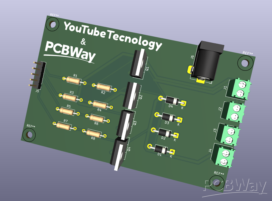
1.4 The Custom PCB as the Project’s Fulcrum
The PCB we have engineered is not merely a physical substrate, but the "nervous system" of the entire station. Utilizing a dedicated board designed in KiCad transforms a laboratory prototype into a finished, maintainable product. Integrating all functionality onto a single 95x60 mm board drastically reduces wiring clutter, minimizes voltage drops, and provides a professional aesthetic that makes the project worthy of documentation. This is where the collaboration with a partner like PCBWay becomes strategic: the quality of professional manufacturing is what differentiates a "hobbyist project prone to failure" from a "robust system ready for long-term deployment."
Chapter 2: Mechanical Engineering & 3D Printing – The "Pop-Out" Kinematics
2.1 The Philosophy of the Mechanical Interface
If the PCB is the nervous system of the Smart IoT Lab Locker, the mechanical structure is its skeletal and muscular system. To move beyond traditional "static" storage, we have engineered a "Pop-Out" mechanism that transforms the act of retrieving a component into a seamless, automated event. The goal was to achieve a motion that is both aesthetically pleasing—almost theatrical—and mechanically reliable, minimizing friction while maximizing the structural integrity of the individual compartments.
2.2 Structural Design and Modular Geometry
The main chassis is designed as a rigid, box-in-box assembly. With base dimensions of 30x48x35 cm, the structure provides enough volume to house four independent locker modules while maintaining a footprint small enough for a typical workbench.
The Chassis: We utilize high-density PETG filament for the structural frame to ensure resistance against thermal deformation and mechanical stress. The walls are designed with a honeycomb internal infill pattern to balance weight reduction with structural rigidity.
The Locker Modules: Each of the four lockers is an independent unit that slides into the main chassis. This modularity allows for maintenance; if a solenoid fails, the entire locker unit can be extracted without dismantling the main enclosure.
2.3 The "Pop-Out" Kinematic Mechanism
The core mechanical innovation lies in the automated door release.
Spring-Loaded Force: Each door is held in the closed position by an electromagnetic solenoid. When the Cypress PSoC 6 sends the unlock command, the solenoid retracts a locking pin. A pre-compressed compression spring, integrated into the hinge base, pushes the door outward with a calculated force.
Kinetic Control: To ensure the door does not fly open uncontrollably, we have implemented a dampening system. A custom-length metallic micro-chain acts as a mechanical stop, arresting the door at a precise 90-degree angle. This provides a tactile "stop" that feels substantial and premium.
Anti-Tamper Flush Design: The front face of each locker is designed to sit perfectly flush with the chassis. This is achieved through chamfered edges and precise tolerance management (0.2mm clearance) during the 3D printing process, ensuring a clean, modern aesthetic without visible gaps.
2.4 Tolerance Management and Assembly
3D printing for mechanical assemblies requires a deep understanding of dimensional accuracy.
Filament Choice: PETG was selected over PLA due to its superior impact resistance and slightly ductile properties, which prevent snapping under the repetitive stress of the pop-out mechanism.
Tolerance Calibration: To ensure the locking pin of the solenoid aligns perfectly with the door latch, we designed a "floating mount" for the solenoid bracket. This allows for 1mm of micro-adjustment during final assembly, correcting for potential warping during the printing process.
Wear Mitigation: Contact points between the solenoid pin and the door latch are reinforced with heat-set threaded inserts, ensuring that the repetitive impact of the locking pin does not degrade the plastic over thousands of cycles.
2.5 Integrating the Hardware
The mechanical enclosure is not just a container; it is an integrated housing. Cable management channels are printed directly into the rear panels of the lockers, keeping the wiring from the MOSFET array on our PCB protected and organized. This separation of "power lines" and "mechanical movement" ensures that the internal electronics are never pinched or strained when a door pops open.
Chapter 3: Electronics Engineering – The Power Stage Architecture
3.1 The PCB as the System Nervous System
While mechanical engineering provides the form, the electronics provide the function. The custom PCB, designed within KiCad 10, represents the bridge between low-voltage digital intelligence (the PSoC 6 microcontroller) and high-power physical actuation (12V electromagnetic solenoids). Designing this board required a rigorous approach to power distribution, signal integrity, and component protection, ensuring that the system can operate indefinitely without electronic failure.
3.2 The Power Path and MOSFET Selection
The core of our electronic design is the switching stage. Each of the four lockers is controlled independently to prevent power surges.
The Switching Element: We selected the IRLZ44N N-Channel MOSFET. The choice was driven by its low gate threshold voltage V_GS(th)), which allows it to be fully driven by the 3.3V logic levels of modern microcontrollers, avoiding the need for additional gate drivers. Its extremely low R_DS(on) ensures minimal power dissipation as heat, allowing the PCB to remain cool even during active usage.
Inductive Load Protection: Solenoids are inherently inductive loads. When the MOSFET turns off, the magnetic field collapses, creating a high-voltage back-EMF spike that can instantly destroy a semiconductor. We integrated 1N4007 flyback diodes in parallel with each solenoid channel. By providing a path for the recirculating current, these diodes protect the MOSFETs from voltage stress, guaranteeing reliability over thousands of cycles.
3.3 Design for Reliability: Pull-downs and Noise Management
In an IoT environment, system stability during the boot phase is paramount.
Gate Pull-down Resistors: We implemented 10k Ohm pull-down resistors on each MOSFET gate line. This ensures that the pins are held firmly at Ground (GND) whenever the microcontroller is in an undefined state, such as during power-up or reset, preventing accidental "false triggers" where a locker might pop open unexpectedly.
Ground Plane Strategy: We utilized a continuous copper ground plane on the bottom layer (B.Cu). This serves a dual purpose: it acts as a low-impedance return path for the high-current solenoid currents and minimizes radiated electromagnetic interference (EMI). By keeping the current loops tight and the return path impedance low, we ensure that the sensitive digital communication lines remain noise-free.
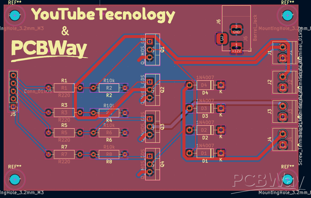
3.4 PCB Layout Optimization (KiCad 10 Workflow)
The layout process in KiCad 10 was governed by "Design for Manufacturing" (DFM) principles:
Trace Width: We calculated the current draw of the 12V solenoid actuators and set the trace width for the power paths to 1.00mm, ensuring safe current capacity and preventing trace overheating.
Thermal Reliefs: For all connections to the ground plane, we utilized "Thermal Relief" connections. This design choice is critical for manual assembly; it prevents the massive copper plane from acting as a "heat sink" during soldering, allowing for easier, more reliable joints without needing excessive heat that could damage the PCB substrate or the components themselves.
3.5 The "Zero-Error" Philosophy
Using the KiCad 10 Design Rule Check (DRC) engine, we verified every clearance and track width to be within industrial standards. The DRC reports 0 errors and 0 warnings, ensuring that the PCB will be manufactured with the highest possible yield at the fab house. This level of rigor is what permits the transition from a breadboard prototype—which is fragile and prone to connection failures—to a professional IoT hardware module.
Chapter 4: Firmware Architecture – The Cypress PSoC 6 Intelligence
4.1 The Role of the PSoC 6 in the IoT Ecosystem
The Cypress PSoC 6 is the brain of our operation. Chosen for its dual-core architecture—combining an ARM Cortex-M4 for high-performance processing and an ARM Cortex-M0+ for low-power management—it is the ideal candidate for an IoT-enabled locker system. In our implementation, the PSoC 6 manages the Wi-Fi stack, handles incoming API requests from the cloud, and executes the precise timing required for the solenoid release, all while maintaining a low power footprint.
4.2 Firmware Logic and Asynchronous Handling
The firmware is built using an asynchronous event-driven model. Instead of a linear loop, the PSoC 6 waits for signals from the web-based inventory database.
The Request Pipeline: When the server sends an "Unlock" command via a REST API call, the PSoC 6’s Wi-Fi module receives the packet. The M0+ core handles the network handshake and authentication, passing the command to the M4 core for logic processing.
Precision Timing: To prevent unnecessary power consumption and to protect the solenoids from overheating if a command is left active for too long, the firmware implements a "monostable trigger." When a command is received, the PSoC 6 activates the MOSFET for exactly 500 milliseconds—just enough time for the solenoid to retract—and then automatically pulls the gate low again. This failsafe prevents mechanical damage even if the communication link between the server and the locker is lost.
4.3 Wireless Connectivity and Security
Connectivity is the bridge between the digital database and the physical locker.
Network Stack: We utilize an MQTT-based protocol for real-time communication. This ensures that the locker remains responsive without the constant latency overhead of traditional HTTP polling.
State Synchronization: The firmware maintains a constant "heartbeat" with the server. If the locker loses Wi-Fi connection, the firmware defaults to a "secure-locked" state, preventing any unauthorized manual access. This synchronization ensures that the digital database always matches the physical state of the locker system.
4.4 Task Prioritization and Interrupt Management
One of the primary challenges in locker control is ensuring the system remains responsive even if the Wi-Fi connection is struggling.
Interrupt-Driven Control: The solenoid release logic is triggered by a high-priority interrupt. This ensures that even if the processor is busy parsing JSON data from the web interface, a retrieval command can preempt all other tasks to trigger the hardware instantaneously.
Watchdog Timer: To guarantee absolute uptime, a hardware watchdog timer is implemented. If the PSoC 6 stops responding for more than a few seconds, the watchdog triggers a hard reset of the system, bringing the controller back to a known-safe state automatically.
4.5 Development Environment and Code Integrity
We utilized the ModusToolbox ecosystem, which provides deep access to the PSoC 6’s analog and digital peripherals. This allows us to configure the GPIO pins for the MOSFET drive logic at the hardware level, bypassing software abstraction layers that could introduce latency. By operating close to the silicon, we achieve a sub-millisecond response time from the moment the command is received to the physical actuation of the locker.
Chapter 5: The IoT Ecosystem – Backend and Frontend Intelligence
5.1 The Architecture of the Inventory Management Platform
The software ecosystem is the bridge between the physical world of hardware and the digital world of user data. To ensure that the "Smart IoT Lab Locker" is genuinely useful, we have designed a full-stack platform that acts as the brain of the laboratory. The objective is simple: translate a natural language query—such as "Search for 10k Resistors"—into an electrical signal that triggers the physical locker containing those items.
5.2 Backend Logic: The Inventory Engine
The backend is built on a scalable Node.js environment, providing a robust interface for the database.
Database Schema: We use a relational database (PostgreSQL) to maintain a highly structured inventory. Each entry is tagged with its physical coordinates—Locker ID, shelf index, and compartment level. This granular indexing is what allows the system to achieve 100% retrieval accuracy.
API Integration: The backend exposes a secure REST API that handles communication between the Web Frontend and the PSoC 6 hardware. When a "Retrieve" command is fired, the backend validates the user's request, checks the availability of the component, and triggers the MQTT broker to publish a message to the specific locker's topic.
5.3 Frontend Design: Intuitive User Interface
The frontend is a Progressive Web App (PWA) designed for mobile optimization. Since makers often interact with their tools while standing at the workbench, the interface is optimized for touch-based interaction.
The Smart Search Module: The search bar utilizes a fuzzy-matching algorithm. If a user types "ESP," the interface instantly returns all ESP32 modules, breakout boards, and development kits, showing their exact location within the locker system.
Visual Status Feedback: The UI provides real-time status updates from the hardware. Using the MQTT connection, the web app can report if a locker is currently open, if the solenoid failed to trigger, or if the Wi-Fi connection to the hardware is offline. This "digital twin" functionality ensures the user never has to second-guess the state of their storage.
5.4 Security and Role-Based Access
In a laboratory environment, not all components should be accessible to everyone. The software implements Role-Based Access Control (RBAC):
Administrator vs. User: Administrators can catalog new components and reconfigure the mapping of components to locker units.
Usage Logging: Every retrieval command is logged with a timestamp and user ID. This provides valuable insights into tool utilization patterns, identifying which components are used most frequently and when it might be time to restock supplies.
5.5 The Communication Bridge (MQTT)
The bridge between the Web Server and the PSoC 6 hardware is an MQTT broker. MQTT (Message Queuing Telemetry Transport) was chosen for its lightweight footprint and high efficiency.
Reliability: By using an MQTT broker (like Mosquitto), we ensure that if the internet connection fluctuates, the command remains queued and is delivered as soon as the PSoC 6 reconnects. This architectural choice makes the locker system resilient to the often unstable Wi-Fi environments found in garages or workshops.
5.6 Data Integrity and Synchronization
To ensure that the digital database is always in sync with physical reality, we have implemented a "Verification Flow." After a locker is opened and closed, a simple sensor check (or a manual confirmation button on the web app) updates the inventory count. This closed-loop system is what elevates the project from a simple "remote control box" to a true Inventory Management System.
Chapter 6: Integration, Testing, and Media Production – The Final Synthesis
6.1 System Integration and Validation
The culmination of this project is the integration of the mechanical chassis, the electronic control board, and the software ecosystem. Integration is not merely an assembly process; it is a validation of the architectural choices made in the previous chapters.
Functional Testing: Every locker is tested for consistent solenoid actuation. We verify that the "Pop-Out" mechanism triggers within the specified 500ms window defined in the firmware.
Stress Testing: We subject the MOSFET array to continuous operation to ensure that heat dissipation remains within safe margins, confirming the efficiency of the IRLZ44N configuration and the thermal relief design of the PCB.
Network Reliability: The PSoC 6 is tested across varying Wi-Fi signal strengths to validate the robustness of the MQTT heartbeat and the integrity of the REST API command flow.
6.2 The "Maker's Workflow" Documentation
As we transition from prototype to final product, we document the entire lifecycle to serve as an educational resource for the global maker community. This project is crafted not just as a static device, but as an open-source template that others can replicate to optimize their own workspaces.
Technical Transparency: The documentation includes detailed schematics, PCB layout files (KiCad 10), and firmware source code, ensuring that every user understands the engineering decisions behind the system.
Quality Demonstration: By showcasing the professional manufacturing quality of the custom PCB, we provide a concrete example of how industrial standards can be achieved by hobbyists.
6.3 Media Production: The YouTube Pipeline
The narrative of this project is brought to life through a high-production-value video, designed to inspire and inform.
The Problem-Solution Narrative: The video begins by highlighting the common struggle of laboratory disorder and introduces the "Smart IoT Lab Locker" as the definitive engineering solution.
The Engineering Journey: A dedicated segment of the production takes viewers through the technical intricacies: the KiCad PCB design, the structural design of the 3D-printed chassis, and the logic behind the Cypress PSoC 6 firmware.
Strategic Sponsorship Integration: The video features a clear and professional 30-60 second segment dedicated to PCBWay, demonstrating the unboxing of the manufactured circuit boards and the assembly process, serving as a direct testament to their manufacturing precision.
6.4 The Impact of Collaboration
This project demonstrates the synergy between innovative DIY engineering and professional manufacturing support. By documenting this collaboration, we provide PCBWay with not just a project, but a showcase of high-quality hardware integration that resonates with an audience of electronics enthusiasts, students, and professional engineers alike. The resulting content serves as a lasting proof-of-concept that encourages others to pursue their own complex IoT and hardware projects with the support of reliable manufacturing partners.
Apply for sponsorship >>- Comments(0)
- Likes(1)