SmartDrive-BMS: Battery-Aware BLDC Motor Controller
SmartDrive-BMS: Integrated BLDC/PMSM Motor Drive and Battery Management Platform
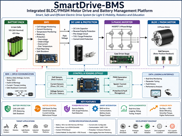
SmartDrive-BMS is a low-voltage electric drive project that integrates a BLDC/PMSM motor controller, three-phase inverter, and Li-ion battery management system into one complete platform.
The goal of this project is to build a practical and safe electric drive system for light electric mobility, robotics, and educational motor-control applications. Instead of treating the motor driver and battery system as two separate parts, this project focuses on integrating them together so the drive can react intelligently to battery voltage, current, temperature, and protection limits.
## Why I started this project
Many small electric-drive projects use a basic motor controller and a separate battery protection board. This often works at low power, but it does not provide enough visibility, safety, or control when the system becomes more demanding.
A complete electric-drive system should not only spin the motor. It should also monitor the battery, protect the power stage, limit current safely, handle braking/reverse operation, and provide useful diagnostic data during testing.
This project is being developed to bridge that gap.
Main system architecture
The system consists of:
- Li-ion battery pack
- Battery Management System (BMS)
- DC-link protection and filtering
- Three-phase MOSFET inverter
- Gate driver stage
- BLDC/PMSM motor
- Hall sensor feedback
- Current and voltage sensing
- STM32-based embedded controller
- Speed/current control algorithms
- Fault detection and protection logic
- Serial data logging for testing and analysis
The basic power flow is:
Battery Pack → BMS → DC Link → 3-Phase Inverter → BLDC/PMSM Motor
The controller receives feedback from Hall sensors, current sensors, voltage sensing circuits, and temperature sensors. Based on these measurements, it controls the inverter switching and protects the system during abnormal conditions.
Control strategy
The first control stage uses Hall-sensor-based six-step commutation. This allows reliable startup and practical validation of the inverter, gate driver, Hall decoding, PWM generation, and protection logic.
The control system includes:
- Hall-based sector detection
- Six-step commutation
- PWM duty control
- Closed-loop speed regulation
- Current limiting
- Bidirectional torque operation
- Electrical braking / reverse torque support
- Fault shutdown logic
After validating the six-step control stage on hardware, the next upgrade path is Field-Oriented Control (FOC) for smoother torque, better efficiency, and improved dynamic response.
BMS integration
A key feature of this project is the integration between the motor drive and the battery management system.
The BMS side is planned to include:
- Cell voltage monitoring
- Pack voltage monitoring
- Charge/discharge current sensing
- Overvoltage protection
- Undervoltage protection
- Overcurrent protection
- Temperature monitoring
- Balancing strategy
- Fault reporting
- Safe shutdown control
The long-term goal is to make the motor controller battery-aware. This means the motor drive can reduce torque, limit current, or shut down safely based on the battery state instead of waiting for a hard protection cutoff.
For example:
- Low battery voltage → reduce maximum motor current
- High battery temperature → reduce torque demand
- High discharge current → activate current limiting
- Full battery during braking → limit regenerative braking
- Critical fault → controlled shutdown
This makes the system safer and more realistic for real-world electric mobility and robotics applications.
Current project status
The project is currently in the design and validation stage.
Completed or in progress:
- Motor parameters collected and studied
- Hall sensor sequence and six-step commutation table verified
- MATLAB/Simulink control model under development
- Bidirectional six-step control logic developed
- Speed/current control structure planned
- BMS and protection architecture planned
- STM32-based controller selected as the embedded platform
- Power stage and battery protection circuits being evaluated
- Hardware prototype roadmap prepared
The next major step is to build and test the first hardware prototype, including the inverter power stage, sensing circuits, protection circuits, and embedded control firmware.
What makes this project useful
This project is useful because it combines several important engineering areas into one complete system:
- Power electronics
- Motor drives
- Embedded systems
- Battery management
- Control systems
- Protection design
- PCB design
- Practical testing and debugging
It is not only a theoretical motor-control project. The objective is to create a validated prototype that can be tested, measured, improved, and demonstrated.
Planned development stages
1. Build the first three-phase inverter prototype
2. Validate gate driver signals and PWM switching
3. Test Hall-based six-step commutation
4. Add current and voltage sensing
5. Implement closed-loop speed control
6. Add current limiting and protection logic
7. Integrate BMS monitoring and fault handling
8. Build a clean PCB version
9. Add data logging and diagnostics
10. Upgrade the control algorithm toward FOC
Support needed
To move this project to the next stage, I am looking for support in:
- PCB fabrication
- Electronic components
- MOSFETs and gate drivers
- Current sensors
- Battery monitoring components
- Testing equipment access
- Technical mentorship
- Prototype manufacturing support
This support will help transform the project from a simulation and design-stage concept into a tested hardware prototype.
Final goal
The final goal is to develop a smart, safe, and practical BLDC/PMSM electric drive platform with integrated BMS protection and battery-aware control.
This platform can be used as a foundation for light electric vehicles, robotics, educational motor-control systems, and low-voltage industrial motion applications.
Apply for sponsorship >>- Comments(0)
- Likes(1)