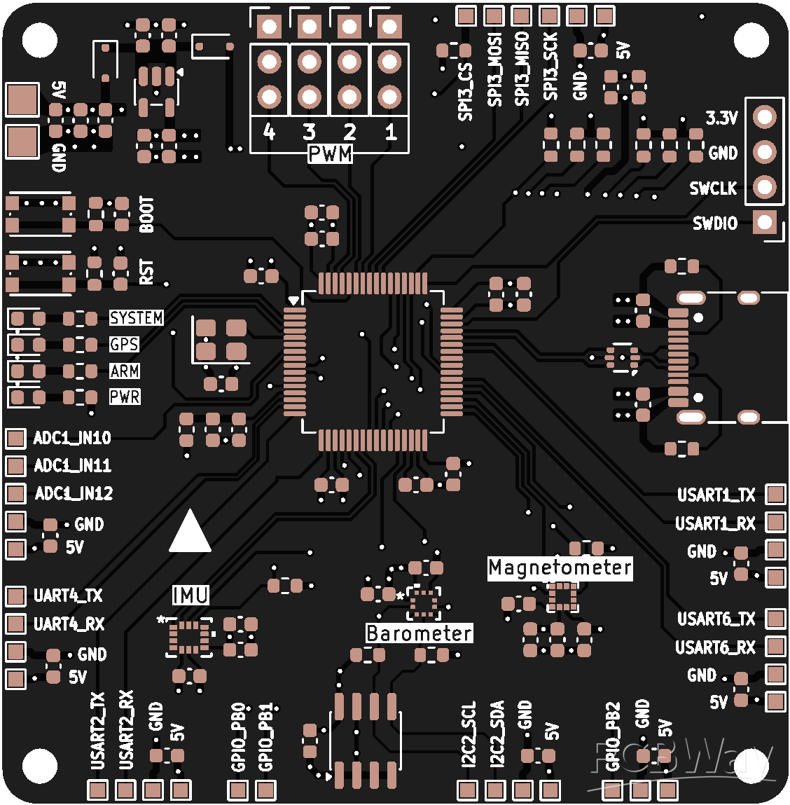
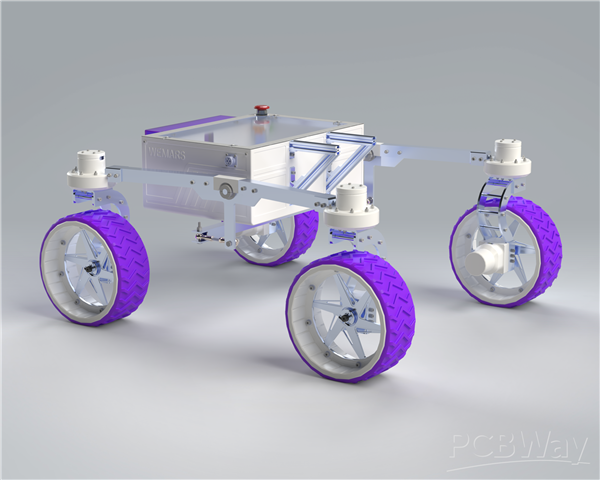
Power Distribution and Logic Control Board
Project Vision
Modern autonomous robotic systems and unmanned ground vehicles (UGVs) demand an electronics architecture capable of handling two fundamentally different engineering requirements simultaneously: high-current power distribution and low-noise deterministic real-time control. Most commercial power distribution systems are modular in nature, forcing robotics teams to integrate multiple external converters, logic boards, sensor interfaces, protection circuits, and communication modules. This approach introduces excessive wiring complexity, increased electromagnetic interference (EMI), thermal inefficiencies, additional points of failure, and poor scalability for advanced robotic applications.
To address these limitations, we designed and developed a fully custom Integrated Power Distribution and Logic Control Board engineered specifically for high-performance robotics platforms operating in electrically noisy and mechanically demanding environments.
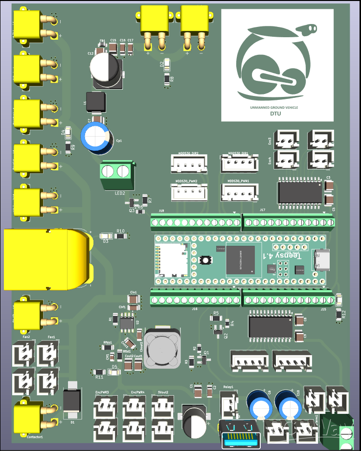
The PCB acts as the central electrical backbone of the robotic system, integrating:
- intelligent power management,
- real-time embedded control,
- signal conditioning,
- voltage regulation,
- EMI suppression,
- telemetry monitoring,
- and industrial-grade connectivity
into a single compact and highly optimized architecture.
Unlike traditional robotics electronics stacks that rely on multiple disconnected modules, this system consolidates the entire low-level electrical infrastructure into one unified platform optimized for reliability, maintainability, and real-world deployment.
System Architecture Overview
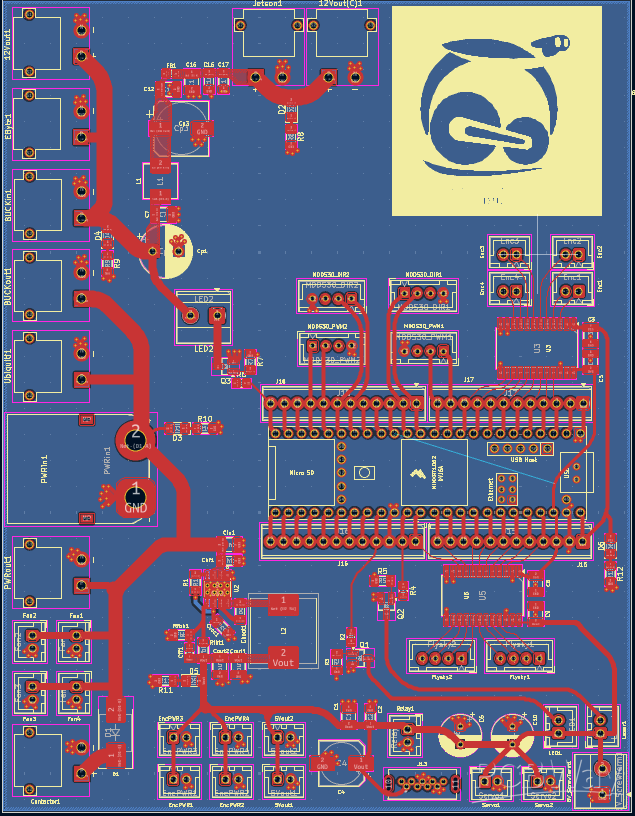
The board architecture was designed using a segmented mixed-signal layout methodology, where high-current power electronics and sensitive digital logic are electrically and physically isolated to minimize conducted and radiated noise coupling.
The system is divided into two primary domains:
1. High-Power Distribution and Regulation Section
This domain handles:
- high-current battery input,
- DC power conversion,
- regulated voltage distribution,
- transient suppression,
- filtering,
- and thermal power management.
The power section was optimized for:
- low ripple,
- reduced switching noise,
- high conversion efficiency,
- and stable voltage delivery under dynamic robotic loads.
2. Embedded Logic and Real-Time Control Section
This domain manages:
- encoder acquisition,
- PID computation,
- logic-level conversion,
- real-time motion control,
- signal integrity,
- and communication with motor drivers and compute hardware.
The control section was intentionally routed away from switching regulators and high-current traces to preserve signal integrity and reduce EMI-induced timing instability.
Power Input and Distribution Architecture
The system operates from a 6S LiPo battery source, providing:
- 22.2V nominal
- 25.2V fully charged
This high-energy input is distributed across multiple isolated power domains through carefully engineered copper pours and current-optimized routing paths.
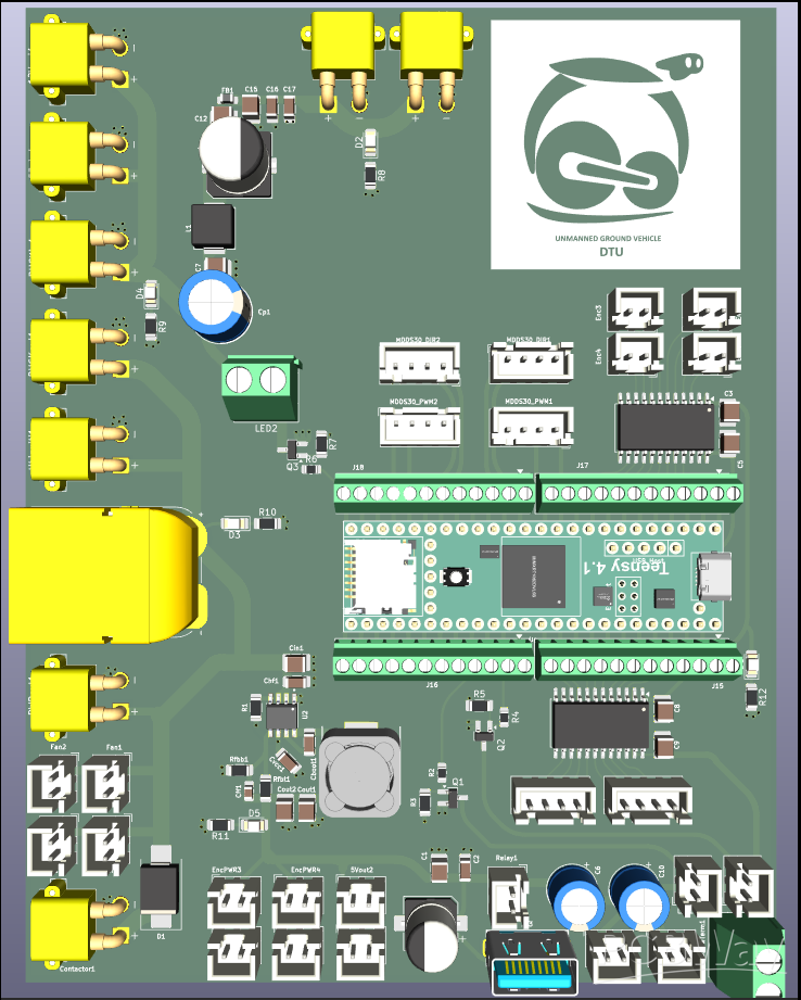
To ensure reliable operation under high vibration and large current transients, industrial-grade:
- XT60
- XT90
- JST connectors
were selected instead of conventional header pins or Dupont connectors.
These connectors provide:
- superior mechanical retention,
- lower contact resistance,
- reduced connector heating,
- and improved reliability in high-vibration robotic environments.
Multi-Rail Power Conversion System
The PCB distributes incoming battery power into three dedicated voltage domains optimized for different subsystems.
Direct Battery Rail
A direct unregulated battery rail is exposed for high-current drivetrain systems such as:
- motor drivers,
- contactors,
- and propulsion electronics.
This minimizes unnecessary conversion losses while maintaining maximum drivetrain efficiency.
The raw battery rail uses:
- wide copper pours,
- reduced loop-area routing,
- and reinforced high-current paths
to safely handle transient current spikes generated during acceleration and stall conditions.
Regulated 12V Compute Rail
A dedicated low-noise 12V rail powers:
- the NVIDIA Jetson Orin Nano Super,
- cooling systems,
- auxiliary compute hardware,
- and onboard high-power peripherals.
AI compute modules are highly sensitive to:
- voltage sag,
- ripple noise,
- and transient spikes.
To ensure stable operation, the 12V power stage integrates:
- bulk capacitance,
- low-ESR ceramic decoupling capacitors,
- transient filtering,
- and carefully controlled return-current paths.
Special attention was given to minimizing:
- switching-node radiation,
- ground bounce,
- and power ripple
to prevent compute instability during high-load robotic maneuvers.
Regulated 5V Peripheral Rail
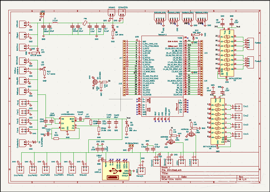
Peripheral electronics are powered through a dedicated high-efficiency 5V rail generated using the:
LMR33640AR Automotive-Grade Buck Converter
from Texas Instruments.
The LMR33640AR was selected specifically because of:
- its wide input voltage capability,
- high conversion efficiency,
- low EMI emission characteristics,
- thermal robustness,
- and automotive-grade reliability standards.
The regulator stage was designed using advanced switching-layout techniques including:
- minimized switching-loop geometry,
- tightly coupled input capacitor placement,
- optimized feedback routing,
- and thermal via stitching.
To further improve power quality, the design incorporates:
- LC filtering stages,
- low-pass decoupling networks,
- and distributed bypass capacitance
to suppress high-frequency switching noise before power reaches sensitive peripherals.
Additional LCR-based DC filtering networks were implemented on critical logic rails to reduce:
- voltage ripple,
- transient overshoot,
- and conducted EMI propagation across the board.
This significantly improves power integrity for:
- wireless emergency-stop systems,
- laser modules,
- servos,
- and communication peripherals.
Power Monitoring and Intelligent Telemetry
Reliable autonomous systems require continuous awareness of electrical operating conditions. To achieve this, the PCB integrates the:
INA219AIDCNR Current and Voltage Monitoring IC
The INA219 continuously measures:
- voltage supplied to the Jetson,
- current consumption,
- and instantaneous power draw.
This telemetry allows the system to:
- detect brownout conditions,
- monitor compute load behavior,
- estimate battery health,
- identify abnormal current spikes,
- and trigger software-based protective responses before catastrophic failures occur.
Real-time power telemetry is especially critical in autonomous robotics where sudden voltage collapse can cause:
- compute shutdowns,
- navigation failures,
- or complete system instability.
Embedded Real-Time Control System
At the core of the logic section is the:
Teensy 4.1 High-Performance Microcontroller
The Teensy 4.1 was selected because of:
- deterministic real-time processing,
- extremely low interrupt latency,
- high-frequency encoder processing capability,
- and robust robotics ecosystem support.
The system follows a distributed processing architecture where:
- the NVIDIA Jetson Orin Nano Super handles high-level AI operations,
- while the Teensy executes deterministic low-level control loops.
The Jetson performs:
- computer vision,
- SLAM,
- AI inference,
- path planning,
- and navigation,
while the Teensy independently manages:
- encoder acquisition,
- wheel odometry,
- PID control computation,
- actuator response,
- and motion stabilization.
This separation prevents compute-intensive AI workloads from interfering with time-critical motor control loops.
Encoder Signal Conditioning and Logic-Level Translation
Encoder precision directly impacts:
- odometry accuracy,
- localization quality,
- and autonomous navigation performance.
Many industrial encoders output 5V logic while the Teensy operates at 3.3V. To ensure safe and noise-resistant interfacing, the PCB integrates the:
SN74LVC8T245 Bidirectional Logic-Level Translator
This stage performs:
- bidirectional voltage translation,
- signal buffering,
- impedance isolation,
- and logic stabilization.
Encoder traces were routed using:
- controlled trace spacing,
- short return paths,
- and EMI-aware routing topology
to minimize signal corruption from nearby switching regulators and motor-current paths.
Additionally, curved trace routing techniques were implemented in critical high-speed signal regions to reduce sharp-angle impedance discontinuities and improve signal-flow smoothness across sensitive digital lines.
PID Motion Control Workflow
The motion-control architecture operates as a high-frequency closed-loop feedback system.
Encoder pulses generated by wheel motion first pass through the SN74LVC8T245 translation stage where logic levels are stabilized and conditioned before entering the Teensy microcontroller.
The Teensy continuously calculates:
- wheel velocity,
- rotational direction,
- acceleration behavior,
- and positional feedback
using high-speed interrupt-driven encoder acquisition.
A real-time PID control loop then compares:
target motion parameters against measured system response.
Corrective outputs are dynamically generated and transmitted to motor drivers to minimize control error and maintain:
- stable motion,
- smooth acceleration,
- accurate trajectory tracking,
- and precise robotic movement.
This architecture enables deterministic low-latency drivetrain control critical for autonomous robotics applications.
EMI Mitigation and Signal Integrity Engineering
Electromagnetic interference is one of the most significant challenges in mixed-signal robotic systems containing:
- switching regulators,
- motors,
- high-current paths,
- and sensitive digital logic.
To combat this, the PCB was engineered using advanced EMI-reduction methodologies including:
- segmented ground architecture,
- controlled current-return paths,
- differential signal isolation,
- and localized filtering networks.
The PCB layout separates:
- high-current power regions,
- switching regulator zones,
- and logic-control domains
- to reduce conducted and radiated interference coupling.
Critical signal lines were isolated from noisy switching nodes using:
- ground shielding strategies,
- optimized trace spacing,
- and short signal-return geometries.
Multiple decoupling stages and distributed ceramic bypass capacitors were strategically placed near IC power pins to suppress transient switching noise at the source.
The result is a highly stable mixed-signal platform capable of maintaining reliable operation even in electrically aggressive environments.
Thermal and Mechanical Reliability
Robotic systems experience continuous vibration, elevated temperatures, dust exposure, and sustained current loading. To ensure long-term reliability, the PCB incorporates:
- heavy copper power routing,
- thermal via arrays,
- reinforced connector anchoring,
- and large copper thermal dissipation zones.
High-current paths were optimized using:
- widened copper pours,
- smooth current-transition geometries,
- and reduced resistance routing techniques
to minimize Joule heating and improve overall efficiency.
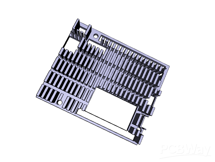
Integrated fan outputs support active thermal management for onboard AI compute systems and high-power electronics.
Engineering Significance
This project represents a fully integrated robotics electronics platform designed specifically for advanced autonomous systems. Rather than functioning as a conventional power board, the system combines:
- intelligent power management,
- embedded control,
- signal integrity engineering,
- EMI mitigation,
- telemetry monitoring,
- and industrial-grade connectivity
into a single unified architecture.
By consolidating multiple independent electronics modules into one optimized PCB, the design achieves:
- reduced system complexity,
- lower overall weight,
- improved reliability,
- enhanced maintainability,
- cleaner wiring architecture,
- and significantly improved electrical robustness.
The platform establishes a scalable foundation for future autonomous robotics development and demonstrates the integration of advanced embedded systems engineering with high-reliability power electronics design.
Future Development Roadmap
With sponsorship support, future revisions of the platform will incorporate:
- advanced multilayer PCB stackups,
- dedicated EMI shielding structures,
- CAN bus integration,
- distributed telemetry systems,
- onboard fault-detection architecture,
- intelligent power sequencing,
- and scalable manufacturing optimization.
Our long-term objective is to evolve this system into a professional-grade robotics electronics platform capable of supporting:
- autonomous ground vehicles,
- industrial robotic systems,
- research platforms,
- defense-oriented unmanned systems,
- and next-generation intelligent robotics architectures.
- Comments(0)
- Likes(7)